
Page 161 - Tunable Lasers Handbook
P. 161
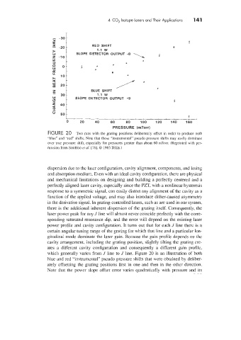
4  CO,  Isotope Lasers and Their Applications   141


                                                                                 t
                                        RED  SHIFT                        #
                                          1.1 w
                                 SLOPE  DETECTOR  OUTPUT  -8
                                                         \  i
                                                             *


                                          1.1  w
                                 SLOPE  DETECTOR  OUTPUT  +9


                                                                                f
                             -1
                             0     20    40     60    80    100    120   140   160
                                                 PRESSURE  (rnTorr)
                     FIGURE 20  Two runs  with the  grating  positions  deliberately  offset in order to produce  00th
                     "blue"  and "red" shifts. Note that these "instrumental"  pseudo pressure  shifts ma)  easily dominate
                     over me pressure shift, especially  for pressures  greater than  about 60 mTorr. (Repnnted 111th per-
                     mission from SooHoo et a1  [76]. 0 1985 IEEE.)


                     dispersion due to the laser configuration, cavity alignment, components, and lasing
                     and absorption medium. Even with an ideal cavity configuration, there are physical
                     and mechanical limitations on designing and building a perfectly centered and a
                     perfectly aligned laser cavity, especially since the PZT, with a nonlinear hysteresis
                     response to a symmetric signal, can easily distort any alignment of  the cavity as a
                     function of  the applied voltage, and may also introduce dither-caused asymmetry
                     in the derivative signal. In grating-controlled lasers, such as are used in our system.
                     there is the additional inherent dispersion of the grating itself. Consequently, the
                     laser power peak for any J line will almost never coincide perfectly with the corre-
                     sponding saturated resonance dip. and the error will depend on the existing laser
                     power profile and cavity configuration. It turns out that for each J  line there is a
                     certain angular tuning range of the grating for which that line and a particular lon-
                     gitudinal mode dominate the laser gain. Because the gain profile depends on the
                     cavity arrangement, including the grating position, slightly tilting the grating cre-
                     ates  a  different  cavity  configuration  and  consequently  a  different  gain  profile,
                     which generally varies from J  line to J  line. Figure 20 is an illustration of  both
                     blue and red ''instrumental" pseudo pressure shifts that were obtained by deliber-
                     alely offsetting the  grating positions  first in  one and then in the other direction.
                     Note that the power  slope offset error varies quadratically with pressure  and its