
Page 212 - Tunable Lasers Handbook
P. 212
190 F.J. Duarte
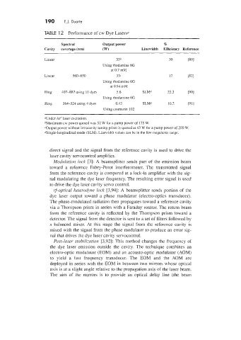
TABLE 12 Performance of cw Dye Laserso
Spectral Output power %
Cavity coverage (nm) 03') Linewidth Efficiency Reference
Linear 33h 30 P91
Using rhodamine 6G
at 0.7 &I
Linear 560-650 33.' 17 WI
Using rhodamine 6G
at 0.91. mM
Ring 407-887 using 11 dyes 5.6 SLW 23.3 ~901
Using rhodamine 6G
Ring 364-524 using 4 d>es 0.43 SLMd 10.1 ~911
Using coumarin 102
oUnder Ar+ laser excitation.
hbfaximum cw power quoted was 52 W for a pump power of 175 W.
COutput power without intracavity tuning prism is quoted at 43 W for a pump power of 200 W.
"ingle-longitudinal mode ISLMI. Linewidth values can be in the few megahertz range.
direct signal and the signal from the reference cavity is used to drive the
laser cavity servocontrol amplifier.
Modulation lock [3]: A beamsplitter sends part of the emission beam
toward a reference Fabry-Perot interferometer. The transmitted signal
from the reference cavity is compared at a lock-in amplifier with the sig-
nal modulating the dye laser frequency. The resulting error signal is used
to drive the dye laser cavity servo control.
t---optical hetel-od~ne lock [3,94]: A beamsplitter sends portion of the
dye laser output toward a phase modulator (electro-optics transducer).
The phase-modulated radiation then propagates toward a reference cavity
via a Thompson prism in series with a Faraday rotator. The return beam
from the reference cavity is reflected by the Thompson prism toward a
detector. The signal from the detector is sent to a set of filters followed by
a balanced mixer. At this stage the signal from the reference cavity is
mixed with the signal from the phase modulator to produce an error sig-
nal that drives the dye laser cavity servocontrol.
Post-laser stabi1i:ation [3,92]: This method changes the frequency of
the dye laser emission outside the cavity. The technique combines an
electro-optic modulator (EOM) and an acousto-optic modulator (AOM)
to yield a fast frequency transducer. The EOM and the ,40M are
deployed in series with the EOM in between two mirrors whose optical
axis is at a slight angle relative to the propagation axis of the laser beam.
The aim of the mirrors is to provide an optical delay line (the beam