
Page 214 - Tunable Lasers Handbook
P. 214
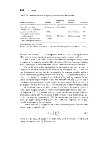
192     F.J.  Duarte


                    TABLE  13  Performance of Frequency-Stabilized cw Dye Lasers

                                                       Frequency   Limiting
                    Stabilization method   Linewidth   drift      factors     Reference

                    Cay18 side lad. Uses   I50 kHza (rms)   50 hlHz/hou         [961
                      two Fabry-Perot interferometers
                    rf-optical hereradyie lock   100 Hz           Sen70 electronics   [91]
                      Uses signals reflected from
                      a reference cavity     <750 Hzn   720 Hz/sec   Mechanical noise   [97]
                    Post-1aAer-  Uses acousto-optic   70 kHz0                   [921
                      and electro-optic modulatorsh
                    UEmission source: ring-dye laser.
                    !'For dye lasers with inmnsic linewidths of -1  MHz. this method has produced linewidths of -1  lcHz [3].


                    Ruddock  and  Bradley  [112]. Subsequently, Fork  et  al.  [113] incorporated the
                    CPM concept to ring cavities, thus demonstrating pulses as short as 90 fs.
                        CPM is established when a colIision between two counterpropagating pulses
                    is induced at the saturable absorber. The interaction of the tu o counterpropagating
                    pulses gives origin to interference that induces a reduction in the pulse duration.
                        Two of  the most widely used cavities in femtosecond dye lasers are the cw
                    linear and  ring  cavity  configurations modified to  incorporate CPM. Linear  and
                    ring femtosecond dye laser cavities incorporating the saturable absorber region in
                    its counterpropagating arrangement is shown in Fig.  13. In both cavities the gain
                    region is configured in the optical axis defined by  M,  and M,,  whereas the sat-
                    urable absorber is deployed in the optical path defined by M,  id M4. Note that in
                    both instances these ultrashort-pulse cavities are equivalent to the linear and ring
                    cw dye laser cavities shown in Fig. 12 with M,  replaced by the CPM arrangement.
                        An  additional feature of  these  cavities  is  the  use  of  intracavity  prism  to
                    induce pulse compression. In dye lasers, pulse broadening by positive group veloc-
                    ity dispersion (GVD) is induced at the dye gain and absorber regions. Multiple-
                    prism arrangements can be configured to provide net positive dispersion, no dis-
                    persion,  or  negative  dispersion  [ 1,1071. In  femtosecond  dye  lasers,  intracavity
                    prisms are deployed to provide negative GVD and hence compensate for the posi-
                    tive GVD generated at the dye regions.
                        Gordon and Fork [ 1041 provide an expression for the group velocity disper-
                    sion constant in a prism array:
                                               D=[&)g,


                    where L is the physical length of the light path, and P is the optical path length
                    through the prism array. By differentiating