
Page 468 - Tunable Lasers Handbook
P. 468
428 Paul Zorabedian
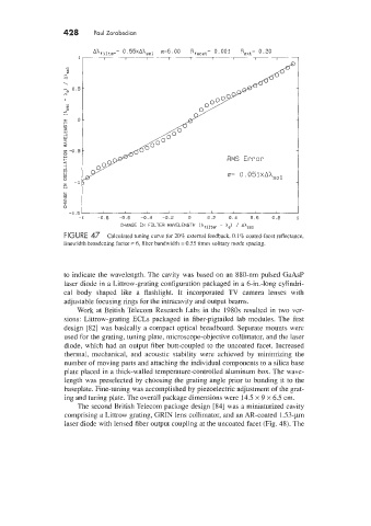
Ahfilter= 0. 55xAASo1 a=6.00 Rfacet= 0.001 ReXt= 0.20
- 1
c
Q
\
- 0.5
x
I
-
x
I O
+
L1
z
W
1
W
>
x
Q.
z -0.5
0 RMS Error
H +
a
1
_J
H
u u= 0.051~Ah,~~
lc
0
-1
z
u
-1 -0.8 -0.6 -0.4 -0.2 0 0.2 0.4 0.6 0.8 1
CHANGE IN FILTER WAVELENGTH (Afilter - A,) / Ah,,,
FIGURE 47 Calculated tuning curve for 20% external feedback. 0.1% coated-facet reflectance,
linewidth broadening factor = 6, filter bandwidth = 0.55 times solitary mode spacing.
to indicate the wavelength. The cavity was based on an 880-nm pulsed GaAsP
laser diode in a Littrow-grating configuration packaged in a 6-in.-long cylindri-
cal body shaped like a flashlight. It incorporated TV camera lenses with
adjustable focusing rings for the intracavity and output beams.
Work at British Telecom Research Labs in the 1980s resulted in two ver-
sions: Littrow-grating ECLs packaged in fiber-pigtailed lab modules. The first
design [82] was basically a compact optical breadboard. Separate mounts were
used for the grating, tuning plate, microscope-objective collimator, and the laser
diode, which had an output fiber butt-coupled to the uncoated facet. Increased
thermal, mechanical, and acoustic stability were achieved by minimizing the
number of moving parts and attaching the individual components to a silica base
plate placed in a thick-walled temperature-controlled aluminum box. The wave-
length was preselected by choosing the grating angle prior to bonding it to the
baseplate. Fine-tuning was accomplished by piezoelectric adjustment of the grat-
ing and tuning plate. The overall package dimensions were 14.5 x 9 x 6.5 cm.
The second British Telecom package design [84] was a miniaturized cavity
comprising a Littrow grating, GRIN lens collimator, and an AR-coated 1.53-pm
laser diode with lensed fiber output coupling at the uncoated facet (Fig. 48). The