
Page 216 - Understanding Automotive Electronics
P. 216
2735 | CH 6 Page 203 Tuesday, March 10, 1998 1:10 PM
SENSORS AND ACTUATORS 6
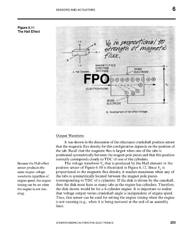
Figure 6.11
The Hall Effect
FPO
Output Waveform
It was shown in the discussion of the reluctance crankshaft position sensor
that the magnetic flux density for this configuration depends on the position of
the tab. Recall that the magnetic flux is largest when one of the tabs is
positioned symmetrically between the magnet pole pieces and that this position
normally corresponds closely to TDC of one of the cylinders.
Because the Hall-effect The voltage waveform V that is produced by the Hall element in the
o
sensor produces the position sensor of Figure 6.10 is illustrated in Figure 6.12. Since V is
o
same output voltage proportional to the magnetic flux density, it reaches maximum when any of
waveform regardless of the tabs is symmetrically located between the magnet pole pieces
engine speed, the engine (corresponding to TDC of a cylinder). If the disk is driven by the camshaft,
timing can be set when then the disk must have as many tabs as the engine has cylinders. Therefore,
the engine is not run- the disk shown would be for a 4-cylinder engine. It is important to realize
ning. that voltage output versus crankshaft angle is independent of engine speed.
Thus, this sensor can be used for setting the engine timing when the engine
is not running (e.g., when it is being motored at the end of an assembly
line).
UNDERSTANDING AUTOMOTIVE ELECTRONICS 203