
Page 214 - Understanding Automotive Electronics
P. 214
2735 | CH 6 Page 201 Tuesday, March 10, 1998 1:10 PM
SENSORS AND ACTUATORS 6
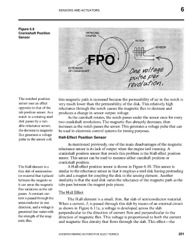
Figure 6.9
Crankshaft Position
Sensor
FPO
The notched position this magnetic path is increased because the permeability of air in the notch is
sensor uses an effect very much lower than the permeability of the disk. This relatively high
opposite to that of the reluctance through the notch causes the magnetic flux to decrease and
tab position sensor. As a produces a change in sensor output voltage.
notch in a rotating steel As the camshaft rotates, the notch passes under the sensor once for every
disk passes by a vari- two crankshaft revolutions. The magnetic flux abruptly decreases, then
able-reluctance sensor, increases as the notch passes the sensor. This generates a voltage pulse that can
the decrease in magnetic be used in electronic control systems for timing purposes.
flux generates a voltage
pulse in the sensor coil. Hall-Effect Position Sensor
As mentioned previously, one of the main disadvantages of the magnetic
reluctance sensor is its lack of output when the engine isn’t running. A
crankshaft position sensor that avoids this problem is the Hall-effect position
sensor. This sensor can be used to measure either camshaft position or
crankshaft position.
The Hall element is a A Hall-effect position sensor is shown in Figure 6.10. This sensor is
thin slab of semiconduc- similar to the reluctance sensor in that it employs a steel disk having protruding
tor material that is placed tabs and a magnet for coupling the disk to the sensing element. Another
between the magnets so similarity is that the steel disk varies the reluctance of the magnetic path as the
it can sense the magnetic tabs pass between the magnet pole pieces.
flux variations as the tab
passes. A constant cur- The Hall Effect
rent is passed through the The Hall element is a small, thin, flat slab of semiconductor material.
semiconductor in one When a current, I, is passed through this slab by means of an external circuit
direction, and a voltage is as shown in Figure 6.11a, a voltage is developed across the slab
generated that varies with perpendicular to the direction of current flow and perpendicular to the
the strength of the mag- direction of magnetic flux. This voltage is proportional to both the current
netic flux. and magnetic flux density that flows through the slab. This effect—the
UNDERSTANDING AUTOMOTIVE ELECTRONICS 201