
Page 217 - Understanding Automotive Electronics
P. 217
2735 | CH 6 Page 204 Tuesday, March 10, 1998 1:10 PM
6 SENSORS AND ACTUATORS
Figure 6.12
Waveform of Hall
Element Output
Voltage for Position
Sensor of Figure 6.10
FPO
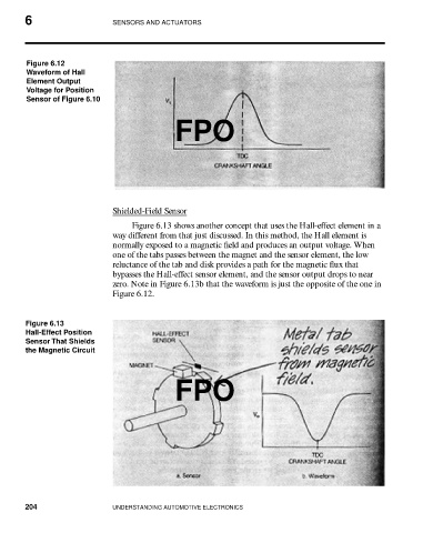
Shielded-Field Sensor
Figure 6.13 shows another concept that uses the Hall-effect element in a
way different from that just discussed. In this method, the Hall element is
normally exposed to a magnetic field and produces an output voltage. When
one of the tabs passes between the magnet and the sensor element, the low
reluctance of the tab and disk provides a path for the magnetic flux that
bypasses the Hall-effect sensor element, and the sensor output drops to near
zero. Note in Figure 6.13b that the waveform is just the opposite of the one in
Figure 6.12.
Figure 6.13
Hall-Effect Position
Sensor That Shields
the Magnetic Circuit
FPO
204 UNDERSTANDING AUTOMOTIVE ELECTRONICS