
Page 212 - Understanding Automotive Electronics
P. 212
2735 | CH 6 Page 199 Tuesday, March 10, 1998 1:10 PM
SENSORS AND ACTUATORS 6
reaches a maximum when the tab is exactly between the pole pieces, and then
decreases as the tab passes out of the pole piece region. In most control systems,
the position of maximum magnetic flux has a fixed relationship to TDC for one
of the cylinders.
The voltage induced in The change in magnetic flux induces a voltage, V , in the sensing coil that
o
the sensing coil varies is proportional to the rate of change of the magnetic flux. Since the magnetic
with the rate of change flux must be changing to induce a voltage in the sensing coil, its output voltage
of the magnetic flux. is zero whenever the engine is not running, regardless of the position of the
When the tab is centered crankshaft. This is a serious disadvantage for this type of sensor because the
between the poles of the engine timing cannot be set statically.
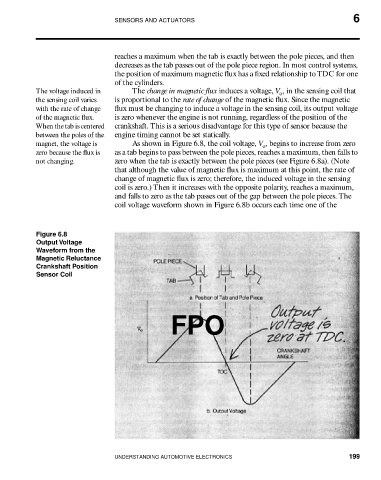
magnet, the voltage is As shown in Figure 6.8, the coil voltage, V , begins to increase from zero
o
zero because the flux is as a tab begins to pass between the pole pieces, reaches a maximum, then falls to
not changing. zero when the tab is exactly between the pole pieces (see Figure 6.8a). (Note
that although the value of magnetic flux is maximum at this point, the rate of
change of magnetic flux is zero; therefore, the induced voltage in the sensing
coil is zero.) Then it increases with the opposite polarity, reaches a maximum,
and falls to zero as the tab passes out of the gap between the pole pieces. The
coil voltage waveform shown in Figure 6.8b occurs each time one of the
Figure 6.8
Output Voltage
Waveform from the
Magnetic Reluctance
Crankshaft Position
Sensor Coil
FPO
UNDERSTANDING AUTOMOTIVE ELECTRONICS 199