
Page 210 - Understanding Automotive Electronics
P. 210
2735 | CH 6 Page 197 Tuesday, March 10, 1998 1:10 PM
SENSORS AND ACTUATORS 6
Magnetic Reluctance Position Sensor
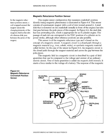
In the magnetic reluc- One engine sensor configuration that measures crankshaft position
tance position sensor, a directly (using magnetic phenomena) is illustrated in Figure 6.6. This sensor
coil wrapped around the consists of a permanent magnet with a coil of wire wound around it. A steel
magnet senses the disk that is mounted on the crankshaft (usually in front of the engine) has tabs
changing intensity of the that pass between the pole pieces of this magnet. In Figure 6.6, the steel disk
magnetic field as the tabs has four protruding tabs, which is appropriate for an 8-cylinder engine. The
of a ferrous disk pass passage of each tab can correspond to the TDC position of a cylinder on its
between the poles of the power stroke, although other reference positions are also possible.
magnet. This sensor is of the magnetic reluctance type and is based on the
concept of a magnetic circuit. A magnetic circuit is a closed path through a
magnetic material (e.g., iron, cobalt, nickel, or synthetic magnetic material
called ferrite). In the case of the sensor in Figure 6.6, the magnetic circuit is
the closed path through the magnet material and across the gap between the
pole pieces.
The magnetic field in a magnetic circuit is described by a pair of field
quantities that can be compared to the voltage and current of an ordinary
electric circuit. One of these quantities is called the magnetic field intensity. It
exerts a force similar to the voltage of a battery. The response of the magnetic
Figure 6.6
Magnetic Reluctance
Crankshaft Position
Sensor
FPO
UNDERSTANDING AUTOMOTIVE ELECTRONICS 197