
Page 172 - Uninterruptible Power Supplies
P. 172
Rotary UPS Systems
170 Chapter Six
~
= ~
=
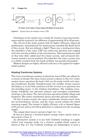
DC Motor driven Rotary Output Stage with Battery Energy Store
Figure 6.1 Typical basic dc machine rotary UPS.
Drawbacks to the system were clearly the brushes’ requiring mainte-
nance and the systems’s low efficiency of approximately 80 to 82 percent.
The advent of the static system with its higher efficiency, improved
performance, and promised low maintenance sounded the death knell
of this circuit. But not without a fight!! There was a brief period when
the reliability of the static UPS was called into question and coupled
with this was the problem of site maintenance. Most maintenance staff
at that time fully understood the rotary system, and advanced elec-
tronics caused a service problem. Provided that the rotary system was
on a fairly constant load, the brush problem was greatly attenuated.
Modern designs are highly efficient and tend to be applied for higher
rated systems.
Rotating Transformer Systems
The rotary transformer systems produced by Anton Piller are offered in
a variety of circuits The basic rotary system is shown in Fig. 6.2. Under
normal mains operation the load is fed via the static switch and rotat-
ing transformer directly. Simultaneously, the rectifier charge ensures
the battery is in the float condition and the inverter is in operation but
not providing power to the rotating transformer. The rotating trans-
former (Uniblock) has alternate primary and secondary transformer
windings in the stator. The rotor provides regulation of both voltage and
frequency. The rotary transformer clearly provides galvanic isolation.
On loss of mains supply the rotary transformer obtains power from
the inverter/battery system, and the static switch isolates the failed
incoming supply. The system is highly efficient, with a claimed figure
of 95 percent, and no waveform distortion is induced onto the incoming
supply.
The output short circuit current is high (14 In).
In lieu of a battery, a flywheel kinetic energy source maybe used as
discussed in Chap. 8.
An alternative system is to use both Uniblock windings to supply
critical and essential loads via a directly coupled diesel engine as
shown in Fig. 6.3. The Uniblock windings are independent in such a
Downloaded from Digital Engineering Library @ McGraw-Hill (www.digitalengineeringlibrary.com)
Copyright © 2004 The McGraw-Hill Companies. All rights reserved.
Any use is subject to the Terms of Use as given at the website.