
Page 176 - Uninterruptible Power Supplies
P. 176
Rotary UPS Systems
174 Chapter Six
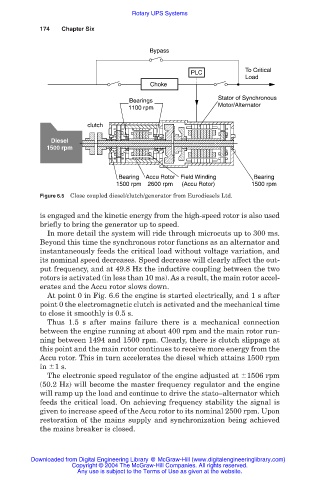
Bypass
To Critical
PLC
Load
Choke
Stator of Synchronous
Bearings
Motor/Alternator
1100 rpm
clutch
Diesel
1500 rpm
Bearing Accu Rotor Field Winding Bearing
1500 rpm 2600 rpm (Accu Rotor) 1500 rpm
Figure 6.5 Close coupled diesel/clutch/generator from Eurodiesels Ltd.
is engaged and the kinetic energy from the high-speed rotor is also used
briefly to bring the generator up to speed.
In more detail the system will ride through microcuts up to 300 ms.
Beyond this time the synchronous rotor functions as an alternator and
instantaneously feeds the critical load without voltage variation, and
its nominal speed decreases. Speed decrease will clearly affect the out-
put frequency, and at 49.8 Hz the inductive coupling between the two
rotors is activated (in less than 10 ms). As a result, the main rotor accel-
erates and the Accu rotor slows down.
At point 0 in Fig. 6.6 the engine is started electrically, and 1 s after
point 0 the electromagnetic clutch is activated and the mechanical time
to close it smoothly is 0.5 s.
Thus 1.5 s after mains failure there is a mechanical connection
between the engine running at about 400 rpm and the main rotor run-
ning between 1494 and 1500 rpm. Clearly, there is clutch slippage at
this point and the main rotor continues to receive more energy from the
Accu rotor. This in turn accelerates the diesel which attains 1500 rpm
in 1 s.
The electronic speed regulator of the engine adjusted at 1506 rpm
(50.2 Hz) will become the master frequency regulator and the engine
will ramp up the load and continue to drive the stato–alternator which
feeds the critical load. On achieving frequency stability the signal is
given to increase speed of the Accu rotor to its nominal 2500 rpm. Upon
restoration of the mains supply and synchronization being achieved
the mains breaker is closed.
Downloaded from Digital Engineering Library @ McGraw-Hill (www.digitalengineeringlibrary.com)
Copyright © 2004 The McGraw-Hill Companies. All rights reserved.
Any use is subject to the Terms of Use as given at the website.