
Page 180 - Uninterruptible Power Supplies
P. 180
Rotary UPS Systems
178 Chapter Six
D3/1 AUTOM. BY-PASS
A
D1/1 D2/1 Static C/O Critical load 1
CHOKE DIESEL B Switch
ROTARY UPS CLUTCH ENGINE
UPS:1 KS1
Close for
Maintenance
D3/2 AUTOM. BY-PASS
A
D1/2 D2/2 Static C/O Critical load 2
CHOKE DIESEL B Switch
ROTARY UPS CLUTCH ENGINE
UPS:1/2 KS/2
A
Static
D3/3 AUTOM. BY-PASS Switch C/O Critical load 3
B
D1/3 D2/3
CHOKE DIESEL
ROTARY UPS CLUTCH ENGINE
UPS:1/3 KS/3
Close for
Maintenance
D3/4 AUTOM. BY-PASS
A
D1/4 D2/4 Static C/O Critical load 4
CHOKE DIESEL B Switch
ROTARY UPS CLUTCH ENGINE
UPS:1/4 KS/4
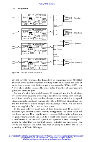
Figure 6.9 Parallel redundant circuit.
at 1500 to 1800 rpm (speed is dependent on mains frequency 50/60Hz).
There is a two-pole three-phase winding in the outer rotor and this, on
excitation, ensures that the inner rotor has a speed of 3000 to 3600 rpm.
A free wheel clutch isolates the outer rotor from the, at this juncture,
quiescent diesel engine.
On loss of mains the circuit breaker Q1 is opened and the dc windings
on the induction coupling are energized and kinetic energy from the high-
speed inner winding ensures that the outer rotor maintains its speed.
Simultaneously, the diesel ramps up to 1500 to 1800 rpm within 2 s or less
and the free wheel clutch engages automatically. Within 10 s the diesel
assumes supplying full power to the system
In the gap between point zero of load transfer and 10 s, power is
obtained by a combination of kinetic energy from the inner rotor and
the diesel engine. This is sufficient to retain a high quality voltage and
frequency regulation to the load. In a short time period the inner rotor
is accelerated to its nominal operational speed of 3000 to 3600 rpm. It
should be noted that the nominal speeds indicated are the speeds rela-
tive to the speed of the outer induction winding and, thus, are in fact
operating at 4500 to 5400 rpm.
Downloaded from Digital Engineering Library @ McGraw-Hill (www.digitalengineeringlibrary.com)
Copyright © 2004 The McGraw-Hill Companies. All rights reserved.
Any use is subject to the Terms of Use as given at the website.