
Page 181 - Uninterruptible Power Supplies
P. 181
Rotary UPS Systems
Rotary UPS Systems 179
MANUAL BYPASS
CHOKE/POWER CABINET
M M D3/1
M M M M
I3/1 D1/1 D2/1 I3/01 M M
MAINS 1 DC1 PDU 1
DA/1 KS 1 DB1
T1 CHOKE/PO WER CABINET M M
CHOKE/POWER CABINET
DTR/1 DA/2 DB2
M M D3/2 DC2
DA/3 M M M M DB3
IA/1
D1/2 D2/2
INPUT KS 2
SWITCHGEAR
NO. 1 CHOKE/POWER CABINET
M M D3/3 CRITICAL
M M M M SPECIAL OUTPUT
CHOKE SWITCH GEAR
D1/3 D2/3
KS 3
MANUAL BYPASS
CHOKE/POWER CABINET
M M D3/4 M M
M M M M DC3
I3/2 D1/4 D2/4 I3/02
IA2
MAINS 2
DA/4 KS 4 DB/4
T2 M M PDU 2
DTR/2 DA/5 CHOKE/POWER CABINET DB/5
M M D3/5 DC4
DA/6 M M M M DB/6
D1/5 D2/5
INPUT KS 5
SWITCHGEAR
NO. 1 CHOKE/POWER CABINET
M M D3/6
M M M M
D1/6 D2/6
KS 6
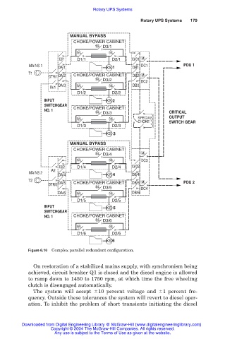
Figure 6.10 Complex parallel redundant configuration.
On restoration of a stabilized mains supply, with synchronism being
achieved, circuit breaker Q1 is closed and the diesel engine is allowed
to ramp down to 1450 to 1750 rpm, at which time the free wheeling
clutch is disengaged automatically.
The system will accept 10 percent voltage and 1 percent fre-
quency. Outside these tolerances the system will revert to diesel oper-
ation. To inhibit the problem of short transients initiating the diesel
Downloaded from Digital Engineering Library @ McGraw-Hill (www.digitalengineeringlibrary.com)
Copyright © 2004 The McGraw-Hill Companies. All rights reserved.
Any use is subject to the Terms of Use as given at the website.