Page 183 - Uninterruptible Power Supplies
P. 183

Rotary UPS Systems
                                                       Rotary UPS Systems  181


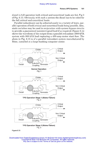
            diesel in full operation both critical and noncritical loads are fed, Fig 3
            of Fig. 6.13. Obviously, with such a system the diesel has to be rated for
            the full critical and noncritical loads.
              Parallel redundancy can be achieved easily in a variety of ways, par-
            allel operation of both critical and noncritical loads being possible. Also,
            static switches may be used in conjunction with system bypass circuits
            to provide a guaranteed noninterrupted load if so required. Figure 6.14
            shows the waveform of the output from a parallel redundant 1600-kVA
            system with 800-kVA load rupturing a 400-amp motor start fuse. The
            photo in Fig. 6.15 is of a parallel redundant system manufactured by
            Hitec, installed at a large banking computer center.


                                                     Critical
                                 Choke
                                                     Output

                                                   Non Critical
                                                     Output
                              Induction
                  Diesel             Generator
                              Coupling
                             Normal Operation
                                  Fig. 1

                                                     Critical
                                 Choke
                                                     Output

                                                   Non Critical
                                                     Output
                              Induction
                  Diesel             Generator
                              Coupling
                     TPS Operation Stage 1 (Mains Failure)
                                  Fig. 2
                                                     Critical
                                 Choke
                                                     Output


                                                   Non Critical
                                                     Output
                              Induction
                  Diesel             Generator
                              Coupling
                     TPS Operation Stage 2 (Mains Failure)
                                  Fig. 3
            Figure 6.13


         Downloaded from Digital Engineering Library @ McGraw-Hill (www.digitalengineeringlibrary.com)
                    Copyright © 2004 The McGraw-Hill Companies. All rights reserved.
                      Any use is subject to the Terms of Use as given at the website.
   178   179   180   181   182   183   184   185   186   187   188