
Page 185 - Uninterruptible Power Supplies
P. 185
Rotary UPS Systems
Rotary UPS Systems 183
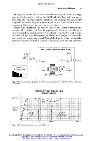
The system consists of a remote diesel consisting of a kinetic energy
store in the form of a rotating flux field inductor/flywheel rotating at
3600 rpm under normal mains operation. The bearings are assisted by
magnetic levitation. A synchronous machine is coupled to an inductor
acting as a filter under normal mains operation.
Figure 6.16 illustrates the basis of the system. Under normal mains
operational condition the load is supplied via inductor and the syn-
chronous machine and inductor act as a filter ensuring the load sees no
spikes or voltage dips. The system, on loss of mains supply, initiates the
start up of the supporting diesel. Meawhile, kinetic energy within the
flywheel/flux field inductor system is ensuring that the synchronous
SPM (SEAMLESS POWER MACHINE)
CB3
UTILITY
ATS
INPUT
LOAD
CB1 CB2
ENGINE-
GENERATOR FFI SF SYNC
CB4 FILTER
FLUX FIELD INDUCTOR
Figure 6.16 Basic circuit diagram of system as manufactured by Perfect Power Systems
California.
FREQUENCY RESPONSE DURING
UTILITY FAILURE
3600 rpm
FFI
SF
1800 rpm
60Hz
UTILITY UTILITY
FAILS RETURNS
0 15 sec time
Figure 6.17 Frequency response on switch over.
Downloaded from Digital Engineering Library @ McGraw-Hill (www.digitalengineeringlibrary.com)
Copyright © 2004 The McGraw-Hill Companies. All rights reserved.
Any use is subject to the Terms of Use as given at the website.