
Page 177 - Uninterruptible Power Supplies
P. 177
Rotary UPS Systems
Rotary UPS Systems 175
RPM
ACCU
50.2
Main
Hz
Rotor
49.8
electric
start
Diesel
0 1 2 3 4 5 6 7
time
forced start seconds
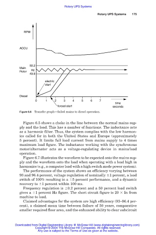
Figure 6.6 Transfer graph—failed mains to diesel operation.
Figure 6.5 shows a choke in the line between the normal mains sup-
ply and the load. This has a number of functions. The inductance acts
as a harmonic filter. Thus, the system complies with the low harmon-
ics called for in both the United States and Europe (approximately
5 percent). It limits full load current from mains supply to 4 times
maximum load figure. The inductance working with the synchronous
motor/alternator acts as a voltage-regulating device in mains/load
operation.
Figure 6.7 illustrates the waveform to be expected onto the mains sup-
ply and the waveform onto the load when operating with a load high in
harmonics (e.g., a computer load with a high switch mode power system).
The performance of the system shows an efficiency varying between
93 and 96.4 percent, voltage regulation of nominally 1 percent, a load
switch of 100% resulting in a 5 percent performance, and a dynamic
recovery to 1 percent within 100 ms.
Frequency regulation is 0.2 percent and a 50 percent load switch
gives a 1 percent Hz figure. The short circuit figure is 20 In from
machine to load.
Claimed advantages for the system are high efficiency (93–96.4 per-
cent), a claimed mean time between failure of 50 years, comparative
smaller required floor area, and the enhanced ability to clear subcircuit
Downloaded from Digital Engineering Library @ McGraw-Hill (www.digitalengineeringlibrary.com)
Copyright © 2004 The McGraw-Hill Companies. All rights reserved.
Any use is subject to the Terms of Use as given at the website.