
Page 249 - Uninterruptible Power Supplies
P. 249
Some System Failures: The Light of Experience!
Some System Failures: The Light of Experience! 247
Contactor
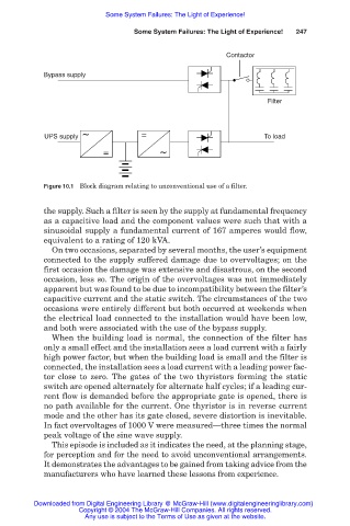
Bypass supply
Filter
~ =
UPS supply To load
= ~
Figure 10.1 Block diagram relating to unconventional use of a filter.
the supply. Such a filter is seen by the supply at fundamental frequency
as a capacitive load and the component values were such that with a
sinusoidal supply a fundamental current of 167 amperes would flow,
equivalent to a rating of 120 kVA.
On two occasions, separated by several months, the user’s equipment
connected to the supply suffered damage due to overvoltages; on the
first occasion the damage was extensive and disastrous, on the second
occasion, less so. The origin of the overvoltages was not immediately
apparent but was found to be due to incompatibility between the filter’s
capacitive current and the static switch. The circumstances of the two
occasions were entirely different but both occurred at weekends when
the electrical load connected to the installation would have been low,
and both were associated with the use of the bypass supply.
When the building load is normal, the connection of the filter has
only a small effect and the installation sees a load current with a fairly
high power factor, but when the building load is small and the filter is
connected, the installation sees a load current with a leading power fac-
tor close to zero. The gates of the two thyristors forming the static
switch are opened alternately for alternate half cycles; if a leading cur-
rent flow is demanded before the appropriate gate is opened, there is
no path available for the current. One thyristor is in reverse current
mode and the other has its gate closed, severe distortion is inevitable.
In fact overvoltages of 1000 V were measured—three times the normal
peak voltage of the sine wave supply.
This episode is included as it indicates the need, at the planning stage,
for perception and for the need to avoid unconventional arrangements.
It demonstrates the advantages to be gained from taking advice from the
manufacturers who have learned these lessons from experience.
Downloaded from Digital Engineering Library @ McGraw-Hill (www.digitalengineeringlibrary.com)
Copyright © 2004 The McGraw-Hill Companies. All rights reserved.
Any use is subject to the Terms of Use as given at the website.