
Page 66 - Uninterruptible Power Supplies
P. 66
Interconnecting the Standby and Normal Supplies
64 Chapter Two
Generator Manual changeover or
circuit mechanically and electrically
Generator breaker interlocked devices
R
Y PME
Normal
B supply
N & E
Local
earth Essential Non-essential
electrode load load
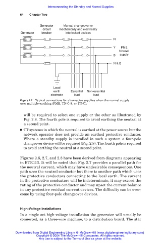
Figure 2.7 Typical connections for alternative supplies when the normal supply
uses multiple earthing (PME, TN-C-S, or TN-C).
will be required to select one supply or the other as illustrated by
Fig. 2.8. The fourth pole is required to avoid earthing the neutral at
a second point.
■ TT systems in which the neutral is earthed at the power source but the
network operator does not provide an earthed protective conductor.
Where a standby supply is installed in such a system a four-pole
changeover device will be required (Fig. 2.8). The fourth pole is required
to avoid earthing the neutral at a second point.
Figures 2.6, 2.7, and 2.8 have been derived from diagrams appearing
in ETR113. It will be noted that Fig. 2.7 provides a parallel path for
the neutral current, which may have undesirable consequences. One
path uses the neutral conductor but there is another path which uses
the protective conductors connecting to the local earth. The current
in the protective conductors will be indeterminate, it may exceed the
rating of the protective conductor and may upset the current balance
in any protective residual current devices. The difficulty can be over-
come by using four-pole changeover devices.
High-Voltage Installations
In a single set high-voltage installation the generator will usually be
connected, as a three-wire machine, to a distribution board. The star
Downloaded from Digital Engineering Library @ McGraw-Hill (www.digitalengineeringlibrary.com)
Copyright © 2004 The McGraw-Hill Companies. All rights reserved.
Any use is subject to the Terms of Use as given at the website.