
Page 70 - Uninterruptible Power Supplies
P. 70
Interconnecting the Standby and Normal Supplies
68 Chapter Two
I
I
Alternator No 1 I
I
3I I
I
I
I
3I
Alternator No 2
I
3I
2I 2I 2I
6I
R Y B N
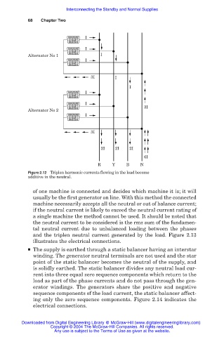
Figure 2.12 Triplen harmonic currents flowing in the load become
additive in the neutral.
of one machine is connected and decides which machine it is; it will
usually be the first generator on line. With this method the connected
machine necessarily accepts all the neutral or out of balance current;
if the neutral current is likely to exceed the neutral current rating of
a single machine the method cannot be used. It should be noted that
the neutral current to be considered is the rms sum of the fundamen-
tal neutral current due to unbalanced loading between the phases
and the triplen neutral current generated by the load. Figure 2.13
illustrates the electrical connections.
■ The supply is earthed through a static balancer having an interstar
winding. The generator neutral terminals are not used and the star
point of the static balancer becomes the neutral of the supply, and
is solidly earthed. The static balancer divides any neutral load cur-
rent into three equal zero sequence components which return to the
load as part of the phase currents and do not pass through the gen-
erator windings. The generators share the positive and negative
sequence components of the load current, the static balancer affect-
ing only the zero sequence components. Figure 2.14 indicates the
electrical connections.
Downloaded from Digital Engineering Library @ McGraw-Hill (www.digitalengineeringlibrary.com)
Copyright © 2004 The McGraw-Hill Companies. All rights reserved.
Any use is subject to the Terms of Use as given at the website.