
Page 81 - Uninterruptible Power Supplies
P. 81
Interconnecting the Standby and Normal Supplies
Interconnecting the Standby and Normal Supplies 79
Protection of the Generator
Small sets up to say 75 kW may be protected against overload and fault
conditions by fuses or by molded-case circuit breakers, and this may
well be the only form of protection used.
For sets above 75 kW the basic form of protection against overloads
is to provide, for each generator, a three-phase overcurrent relay with
an inverse time characteristic and having sufficient delay to allow
downstream protection to operate. To allow positive discrimination
between two relays it is usual to ensure that the two characteristics
provide a time difference between 0.3 and 0.4 s. The shorter time would
be appropriate for installations using modern electronic relays (for
greater accuracy) and quick operating circuit breakers such as those
using vacuum tubes.
For sets above 75 kW the form of protection against faults in the dis-
tribution system is to provide three instantaneous high set overcurrent
elements arranged to operate a timer adjustable up to 5 s. The time
delay is to allow any downstream protection to operate before taking
the somewhat drastic step of shutting down the entire standby supply.
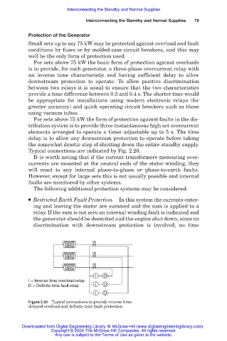
Typical connections are indicated by Fig. 2.20.
It is worth noting that if the current transformers measuring over-
currents are mounted at the neutral ends of the stator winding, they
will react to any internal phase-to-phase or phase-to-earth faults.
However, except for large sets this is not usually possible and internal
faults are monitored by other systems.
The following additional protection systems may be considered:
■ Restricted Earth Fault Protection. In this system the currents enter-
ing and leaving the stator are summed and the sum is applied to a
relay. If the sum is not zero an internal winding fault is indicated and
the generator should be deexcited and the engine shut down; since no
discrimination with downstream protection is involved, no time
I D
I = Inverse time overload relay
D = Definite time fault relay I D
I D
Figure 2.20 Typical connections to provide inverse time-
delayed overload and definite time fault protection.
Downloaded from Digital Engineering Library @ McGraw-Hill (www.digitalengineeringlibrary.com)
Copyright © 2004 The McGraw-Hill Companies. All rights reserved.
Any use is subject to the Terms of Use as given at the website.