
Page 82 - Uninterruptible Power Supplies
P. 82
Interconnecting the Standby and Normal Supplies
80 Chapter Two
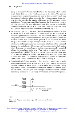
delay is necessary. Downstream faults do not have any effect on the
relay, hence the use of the word restricted in the name. The system
requires four current transformers, one in the neutral which can
be mounted in the terminal box or in the switchgear, and three cur-
rent transformers in the phases which are usually mounted in the
switchgear. The area protected lies between the three-phase current
transformers and the neutral transformer. The system is applicable
to sets of above say 100 kW. It is sometimes known as a balanced cur-
rent system. Typical connections are indicated by Fig. 2.21.
■ Differential Current Protection. In this system the currents at the
start and finish of each phase of the stator windings are compared. If
any of the phases is not balanced, this indicates an internal fault and
the generator should be deexcited and the engine shut down; since no
discrimination with downstream protection is involved, no time
delay is necessary. The system requires the three ends of the stator
winding to be brought out of the stator and into the neutral terminal
box and the installation of three current transformers in the box, the
other three current transformers and the relays are usually mounted
within the associated switchgear. This system is applicable to large
sets, say above 1.5 MW. The area protected lies between the two sets
of current transformers and for this reason the term unit protection
is sometimes used. The term circulating current system is also some-
times used. Typical connections are indicated by Fig. 2.22.
■ Standby Earth Fault Protection. This system is applicable to high-
voltage generators which are resistance earthed. In this system the
current flowing to earth from the star point is monitored and is
applied to a relay. Any current flow indicates a fault and should oper-
ate an inverse time-delayed trip. The system is unrestricted and the
time delay is required to allow any downstream protection to operate.
EF = Instantaneous earth
EF
fault relay
Figure 2.21 Typical connections to provide restricted earth fault
protection.
Downloaded from Digital Engineering Library @ McGraw-Hill (www.digitalengineeringlibrary.com)
Copyright © 2004 The McGraw-Hill Companies. All rights reserved.
Any use is subject to the Terms of Use as given at the website.