
Page 52 - Using ANSYS for Finite Element Analysis Dynamic, Probabilistic, Design and Heat Transfer Analysis
P. 52
composite materials • 39
Y Z
P o
uz = 0; ux = 0;
0° t
90° t
h X
90°
0°
a X
uz = 0;
uy = 0
uz = 0;
uy = 0
uz = 0; ux = 0
a
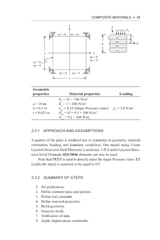
Geometric
properties Material properties Loading
E = 25 × 106 N/m 2
x
a = 10 m E = 1 × 10⁶ N/m 2
y
h = 0.1 m υ = 0.25 (Major Poisson’s ratio) p = 1.0 N/m 2
xy
o
t = 0.025 m G = G = 0.5 × 10⁶ N/m 2
xy
G = 0.2 × 10⁶ N/m 2
yz
2.3.1 APPRoACh AnD ASSUMPTionS
A quarter of the plate is modeled due to symmetry in geometry, material
orientation, loading, and boundary conditions. One model using Linear
Layered Structural Shell Elements is analyzed. 3-D 8-node Layered Struc-
tural Solid Elements SOLID46 elements can also be used.
Note that PRXY is used to directly input the major Poisson’s ratio. EZ
(explicitly input) is assumed to be equal to EY.
2.3.2 SUMMARy oF STePS
1. Set preferences.
2. Define element types and options.
3. Define real constants.
4. Define material properties.
5. Build geometry.
6. Generate mesh.
7. Verification of data.
8. Apply displacement constraints.