Page 30 - Using ANSYS for Finite Element Analysis A Tutorial for Engineers
P. 30

IntroductIon to FInIte element AnAlysIs   •   17
                      Where matrix d is the first minor of [a ] and is matrix [a] with row i and
                                                     ij
                      column j deleted.
                      Finally, determine the inverse


                                               a   ij   −1  =  c [] T
                                                       a

                      1.2.2  elasticity equations

                      1.2.2.1  stress equilibrium equations

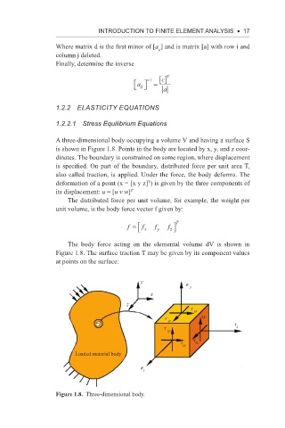
                      A three-dimensional body occupying a volume V and having a surface S
                      is shown in Figure 1.8. Points in the body are located by x, y, and z coor-
                      dinates. The boundary is constrained on some region, where displacement
                      is specified. On part of the boundary, distributed force per unit area T,
                      also called traction, is applied. Under the force, the body deforms. The
                      deformation of a point (x = [x y z] ) is given by the three components of
                                                  T
                      its displacement: u = [u v w] T
                          The distributed force per unit volume, for example, the weight per
                      unit volume, is the body force vector f given by:

                                                          T
                                            f =    f x  f y  f 
                                                         z 
                          The body force acting  on the elemental  volume  dV is shown in
                        Figure 1.8. The surface traction T may be given by its component values
                      at points on the surface:


                                                y            σ
                                                               y
                                                   x
                                           z
                                                               τ  yx
                                                       τ  yz      xy
                                                       τ  zy                τ x

                                                            τ zx  τ xz
                            Loaded material body
                                                σ z


                      Figure 1.8.  Three-dimensional body.
   25   26   27   28   29   30   31   32   33   34   35