
Page 34 - Using ANSYS for Finite Element Analysis A Tutorial for Engineers
P. 34
IntroductIon to FInIte element AnAlysIs • 21
P P
z
σ = 0
τ xz x = 0
τ zy = 0
(a)
P P
z
ε z = 0
γ zx = 0
γ yz = 0
(b)
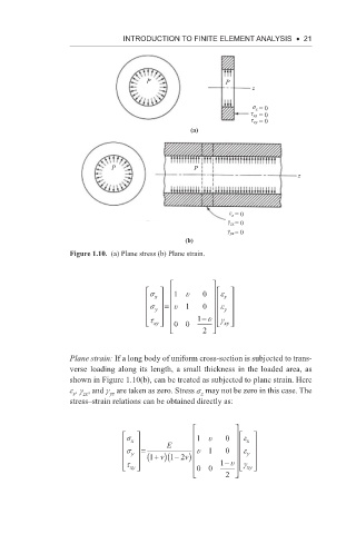
Figure 1.10. (a) Plane stress (b) Plane strain.
s 1 u 0 e
x x
s y = u 1 0 e y
− u
t xy 00 1 g xy
2
Plane strain: If a long body of uniform cross-section is subjected to trans-
verse loading along its length, a small thickness in the loaded area, as
shown in Figure 1.10(b), can be treated as subjected to plane strain. Here
e , g , and g are taken as zero. Stress s may not be zero in this case. The
yz
z
z
zx
stress–strain relations can be obtained directly as:
s 1 u 0 e
e
x E x
s y = u 1 0 e
y
v) − 2
(1 + (1 v) − u
t xy 00 1 g xy
2 