
Page 40 - Using ANSYS for Finite Element Analysis A Tutorial for Engineers
P. 40
IntroductIon to FInIte element AnAlysIs • 27
Post-processing Phase: (sort and display the results)
7. Solve for element stresses and strains.
8. Interpret the results.
1.4 the most Common finite element tyPes
The basic idea of FEA is to make calculations at only limited (finite)
number of points and then interpolate the results for the entire domain
(line, surface, or volume). Any continuous object has infinite degrees of
freedom, and it is just not possible to solve the problem in this format.
FEM reduces the degrees of freedom from infinite to finite with the help
of discretization or meshing (nodes and elements).
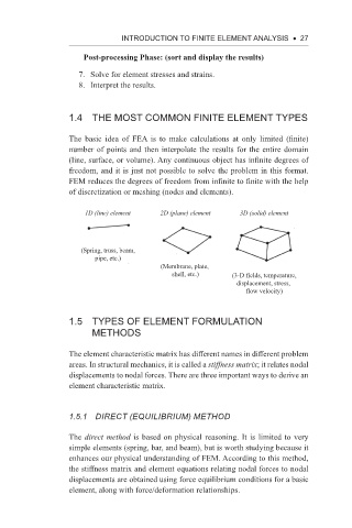
1D (line) element 2D (plane) element 3D (solid) element
(Spring, truss, beam,
pipe, etc.)
(Membrane, plate,
shell, etc.) (3-D fields, temperature,
displacement, stress,
flow velocity)
1.5 tyPes of element formUlation
methods
The element characteristic matrix has different names in different problem
areas. In structural mechanics, it is called a stiffness matrix; it relates nodal
displacements to nodal forces. There are three important ways to derive an
element characteristic matrix.
1.5.1 direct (equiliBriuM) Method
The direct method is based on physical reasoning. It is limited to very
simple elements (spring, bar, and beam), but is worth studying because it
enhances our physical understanding of FEM. According to this method,
the stiffness matrix and element equations relating nodal forces to nodal
displacements are obtained using force equilibrium conditions for a basic
element, along with force/deformation relationships.