
Page 300 - Water Engineering Hydraulics, Distribution and Treatment
P. 300
278
Cross-Connection Control
Chapter 9
pressure
0.0
psia
or
Vacuum pump
psig
39.9´ –14.7 “Zero” absolute
9.7
psia or –5.0 psig
11.5´
14.7 14.7 14.7 psia or
14.7 psia psia psia 0.0 psig
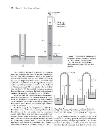
Figure 9.12 (a) Pressure on the free surface
Sea level Sea level
of a liquid at sea level; (b) effect of evacuating
air from a column. Conversion factors:
′
1 = 1ft = 0.3048 m; 1 psia = 6.94 kPa
absolute pressure; 1 psig = 6.94 kPa gauge
(a) (b) pressure.
Figure 9.13a is a diagram of an inverted U-tube that has 4.7 psia
been filled with water and placed in two open containers at
sea level. If the open containers are placed so that the liquid
levels in each container are at the same height, a static state
8.2 psia 10.3 psia
will exist; and the pressure at any specified level in either leg
of the U-tube will be the same. The equilibrium condition
is altered by raising one of the containers so that the liquid 23´
10.3 psia
level in one container is 5 ft (1.52 m) above the level of the 10´
other (see Fig. 9.13b). Because both containers are open to 15´
the atmosphere, the pressure on the liquid surfaces in each
10´
container will remain at 14.7 psia (P = 102 kPa). 14.7
absolute
If it is assumed that a static state exists, momentarily, 5´ psia
within the system shown in Fig. 9.13b, the pressure in the left
tube at any height above the free surface in the left container 14.7 14.7 14.7
psia psia psia
can be calculated. The pressure at the corresponding level in
the right tube above the free surface in the right container
can also be calculated. (a) (b)
As shown in Fig. 9.13b, the pressure at all levels in
Figure 9.13 Pressure relationships in a continuous fluid system
the left tube would be less than at corresponding levels in
(a) at the same elevation; (b) at different elevations. Conversion
the right tube. In this case, a static condition cannot exist ′
factors: 1 = 1ft = 0.3048 m; 1 psia = 6.94 kPa absolute pressure.
because fluid will flow from the higher pressure to the lower
pressure; the flow would be from the right tank to the left Figure 9.14 illustrates how this siphon principle can be
tank. This arrangement is referred to as a siphon. The crest hazardous in a plumbing system. If the supply valve is closed,
of a siphon cannot be higher than 33.9 ft (10.3 m) above the the pressure in the line supplying the faucet is less than the
upper liquid level, because the atmosphere cannot support a pressure in the supply line to the bathtub. Flow will occur,
column of water greater in height than 33.9 ft (10.3 m). therefore, through siphonage, from the bathtub to the open