
Page 303 - Water Engineering Hydraulics, Distribution and Treatment
P. 303
2. The air gap can be easily defeated in the event that
The six basic types of devices that can be used to correct
the two-diameter (2D) requirement was purposely or
cross-connections are as follows:
inadvertently compromised. Excessive splash may be
1. Air gaps
encountered in the event that higher than anticipated
2. Barometric loops
pressures or flows occur. The splash may be a cos-
metic or true potential hazard—the simple solution
3. Vacuum breakers—both atmospheric and pressure
being to reduce the 2D dimension by thrusting the
type
supply pipe into the receiving funnel. By so doing,
4. Double check valves with an intermediate atmo-
the air gap is defeated.
spheric vent
3. At an air gap, we expose the water to the surrounding
5. Double check valve assemblies
air with its inherent bacteria, dust particles, and other
6. Reduced pressure principle devices 9.4 Methods and Devices for the Prevention of Backflow and Backsiphonage 281
airborne pollutants or contaminants. In addition, the
In general, all manufacturers of these devices, with the aspiration effect of the flowing water can drag down
exception of the barometric loop, produce them to one or surrounding pollutants into the reservoir or holding
more of three basic standards, thus ensuring that dependable tank.
devices are being utilized and marketed. The major stan- 4. Free chlorine can come out of treated water as a result
dards in the industry are devised by the American Society of of the air gap and the resulting splash and churn-
Sanitary Engineers (ASSE), the AWWA, and the University ing effect as the water enters the holding tanks. This
of California Foundation for Cross-Connection Control and reduces the ability of the water to withstand bacteria
Hydraulic Research. contamination during long-term storage.
5. For these reasons, air gaps must be inspected as fre-
quently as mechanical backflow preventers. They are
9.4.1 Air Gap
not exempt from an in-depth cross-connection control
Air gaps are nonmechanical backflow preventers that are program requiring periodic inspection of all backflow
very effective devices for use where either backsiphonage devices.
or backpressure conditions may exist. Their use is as old
as piping and plumbing itself, although their design was Air gaps can be fabricated from commercially available
standardized relatively recently. In general, the air gap must plumbing components or purchased as separate units and
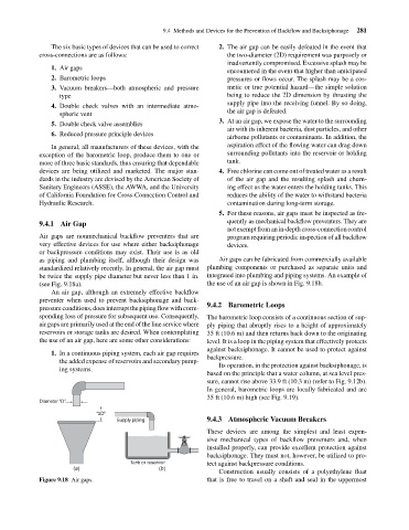
be twice the supply pipe diameter but never less than 1 in. integrated into plumbing and piping systems. An example of
(see Fig. 9.18a). the use of an air gap is shown in Fig. 9.18b.
An air gap, although an extremely effective backflow
preventer when used to prevent backsiphonage and back-
pressure conditions, does interrupt the piping flow with corre- 9.4.2 Barometric Loops
sponding loss of pressure for subsequent use. Consequently, The barometric loop consists of a continuous section of sup-
air gaps are primarily used at the end of the line service where ply piping that abruptly rises to a height of approximately
reservoirs or storage tanks are desired. When contemplating 35 ft (10.6 m) and then returns back down to the originating
the use of an air gap, here are some other considerations: level. It is a loop in the piping system that effectively protects
against backsiphonage. It cannot be used to protect against
1. In a continuous piping system, each air gap requires
backpressure.
the added expense of reservoirs and secondary pump-
Its operation, in the protection against backsiphonage, is
ing systems.
based on the principle that a water column, at sea level pres-
sure, cannot rise above 33.9 ft (10.3 m) (refer to Fig. 9.12b).
In general, barometric loops are locally fabricated and are
35 ft (10.6 m) high (see Fig. 9.19).
Diameter “D”
“2D”
Supply piping 9.4.3 Atmospheric Vacuum Breakers
These devices are among the simplest and least expen-
sive mechanical types of backflow preventers and, when
installed properly, can provide excellent protection against
backsiphonage. They must not, however, be utilized to pro-
Tank or reservoir tect against backpressure conditions.
(a) (b)
Construction usually consists of a polyethylene float
Figure 9.18 Air gaps. that is free to travel on a shaft and seal in the uppermost