
Page 308 - Water Engineering Hydraulics, Distribution and Treatment
P. 308
286
Chapter 9
Cross-Connection Control
(a)
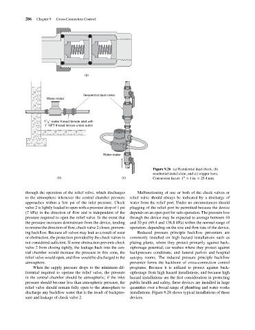
Residential dual check
Water meter
1
1 / 4 ˝ meter thread female inlet with
1˝ NPT thread female union outlet
Water meter
Figure 9.26 (a) Residential dual check, (b)
residential installation, and (c) copper horn.
(b) (c) Conversion factor: 1 = 1in. = 25.4 mm.
′′
through the operation of the relief valve, which discharges Malfunctioning of one or both of the check valves or
to the atmosphere whenever the central chamber pressure relief valve should always be indicated by a discharge of
approaches within a few psi of the inlet pressure. Check water from the relief port. Under no circumstances should
valve 2 is lightly loaded to open with a pressure drop of 1 psi plugging of the relief port be permitted because the device
(7 kPa) in the direction of flow and is independent of the depends on an open port for safe operation. The pressure loss
pressure required to open the relief valve. In the event that through the device may be expected to average between 10
the pressure increases downstream from the device, tending and 20 psi (69.4 and 138.8 kPa) within the normal range of
to reverse the direction of flow, check valve 2 closes, prevent- operation, depending on the size and flow rate of the device.
ing backflow. Because all valves may leak as a result of wear Reduced pressure principle backflow preventers are
or obstruction, the protection provided by the check valves is commonly installed on high hazard installations such as
not considered sufficient. If some obstruction prevents check plating plants, where they protect primarily against back-
valve 2 from closing tightly, the leakage back into the cen- siphonage potential; car washes where they protect against
tral chamber would increase the pressure in this zone, the backpressure conditions; and funeral parlors and hospital
relief valve would open, and flow would be discharged to the autopsy rooms. The reduced pressure principle backflow
atmosphere. preventer forms the backbone of cross-connection control
When the supply pressure drops to the minimum dif- programs. Because it is utilized to protect against back-
ferential required to operate the relief valve, the pressure siphonage from high hazard installations, and because high
in the central chamber should be atmospheric; if the inlet hazard installations are the first consideration in protecting
pressure should become less than atmospheric pressure, the public health and safety, these devices are installed in large
relief valve should remain fully open to the atmosphere to quantities over a broad range of plumbing and water works
discharge any backflow water that is the result of backpres- installations. Figure 9.28 shows typical installations of these
sure and leakage of check valve 2. devices.