
Page 305 - Water Engineering Hydraulics, Distribution and Treatment
P. 305
9.4 Methods and Devices for the Prevention of Backflow and Backsiphonage
Test cock
First check valve
Test cock
3 Gate valve Spring Gate valve 283
/ 4 inch thru 2 inches
1
2 / 2 inches thru 10 inches
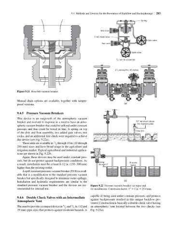
Figure 9.21 Hose bib vacuum breaker.
Manual drain options are available, together with tamper-
proof versions. (a)
9.4.5 Pressure Vacuum Breakers
This device is an outgrowth of the atmospheric vacuum
breaker and evolved in response to a need to have an atmo- 12˝ minimum above
the highest outlet
spheric vacuum breaker that could be utilized under constant
pressure and that could be tested in line. A spring on top
Hose bib
of the disk and float assembly, two added gate valves, test
cocks, and an additional first check were required to achieve
this device (see Fig. 9.22a).
1
These units are available in / through 10 in. (12 through
2
250 mm) sizes and have broad usage in the agriculture and
irrigation market. Typical agricultural and industrial applica-
tions are shown in Fig. 9.22b.
Again, these devices may be used under constant pres-
sure, but do not protect against backpressure conditions. As
Process
a result, installation must be at least 6–12 in. (150–300 mm) At least 6˝ tanks
higher than the existing outlet.
A spill-resistant pressure vacuum breaker (SVB) is avail-
able that is a modification to the standard pressure vacuum
breaker but specifically designed to minimize water spillage.
Installation and hydraulic requirements are similar to the (b)
standard pressure vacuum breaker and the devices are rec- Figure 9.22 Pressure vacuum breaker: (a) types and
ommended for internal use. (b) installations. Conversion factor: 1 = 1in. = 25.4mm.
′′
capable of being used under constant pressure, and protects
9.4.6 Double Check Valves with an Intermediate
Atmospheric Vent against backpressure resulted in this unique backflow pre-
venter. Construction is basically a double check valve having
3
1
The need to provide a compact device in / and / in. (12 and an atmospheric vent located between the two checks (see
2
4
19 mm) pipe sizes that protects against moderate hazards, is Fig. 9.23a).