
Page 301 - Water Engineering Hydraulics, Distribution and Treatment
P. 301
279
9.3 Theory of Backflow and Backsiphonage
where
Valve open
3
3
Q = flow rate, ft /s (m /s)
v = water velocity at section 1, ft/s (m/s)
1
Submerged inlet
v = water velocity at section 2, ft/s (m/s)
2
2
2
A = area of section 1, ft (m )
1
2
2
A = area of section 2, ft (m )
2
As a result, the pressure is reduced. Under such condi-
tions, negative pressures can develop in a pipe. The simple
aspirator is based on this principle. If this point of reduced
pressure is linked to a source of pollution, backsiphonage of
Valve open
the pollutant can occur.
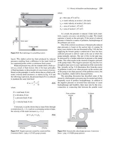
One of the common occurrences of dynamically reduced
Closed supply pipe pressures is found on the suction side of a pump. In
many cases similar to the one illustrated in Fig. 9.16, the line
supplying the booster pump is undersized or does not have
Figure 9.14 Backsiphonage in a plumbing system.
sufficient pressure to deliver water at the rate at which the
pump normally operates. The rate of flow in the pipe may
be increased by a further reduction in pressure at the pump
faucet. This siphon action has been produced by reduced
intake. This often results in the creation of negative pressure
pressures resulting from a difference in the water levels at
at the pump intake. This negative pressure may become low
two separated points within a continuous fluid system.
enough in some cases to cause vaporization of the water in the
Reduced pressure may also be created within a fluid sys-
line. Actually, in Fig. 9.16 illustration, flow from the source
tem as a result of fluid motion. One of the basic principles
of pollution would occur when pressure on the suction side
of fluid mechanics is the principle of conservation of energy.
of the pump is less than pressure of the pollution source, but
Based on this principle, it can be shown that as a fluid accel-
this is backflow, which will be discussed below.
erates (velocity head increases), as shown in Fig. 9.15 and
The preceding discussion has described some of the
the following expression, the pressure head (P∕ ) is reduced
means by which negative pressures may be created and which
to maintain the same total head:
frequently occur to produce backsiphonage. In addition to
P v 2
H = z + + (9.5) the negative pressure or reversed force necessary to cause
2g backsiphonage and backflow, there must also be the cross-
where connection or connecting link between the potable water
H = total head, ft (m)
From pollution To fixture
Z = elevation, ft (m) source
P
= pressure head, ft (m)
v 2
= velocity head, ft (m)
2g
Conversely, it can be shown that as water flows through
a constriction (A < A ) such as a converging section of pipe, +50 psig
1
2
the velocity of the water increases (v < v ):
2
1
Q = v A = v A (9.6)
1 1 2 2 –10
psig
–10 psig
+30 psig +30 psig Booster pump
Figure 9.15 Negative pressure created by constricted flow. Figure 9.16 Dynamically reduced pipe pressure. Conversion
Conversion factor: 1 psig = 6.94 kPa gauge pressure. factor: 1 psig = 6.94 kPa gauge pressure.