
Page 215 - Water Loss Control
P. 215
188 Cha pte r T w e l v e
Prior to testing it is necessary to know what the typical accuracy curve is for each
specific brand, model, and size of meter being tested. This information may be obtained
from the meter manufacturer’s literature. A local chart can be made up which lists the
flow rates at which each type of meter should be tested in order to properly assess its
operating condition. Techniques for performing the tests, selecting the appropriate test
flow rates, determining the accuracies, and reaching conclusions must be known and
carefully followed to obtain valid test results. For positive displacement meters, which
are typically the small residential meters, the AWWA M6 publication provides the three
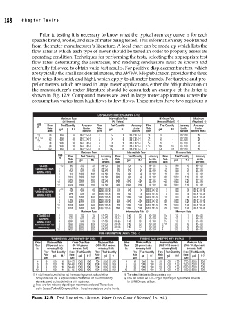
flow rates (low, mid, and high), which apply to all meter brands. For turbine and pro-
peller meters, which are used in large meter applications, either the M6 publication or
the manufacturer’s meter literature should be consulted; an example of the latter is
shown in Fig. 12.9. Compound meters are used in large meter applications where the
consumption varies from high flows to low flows. These meters have two registers: a
DISPLACEMENT METERS (AWWA C700)
Maximum Rate Intermediate Rate Minimum Rate Maximum
(All Meters) (All Meters) (New and Rebuilt) 1 (Repaired) 1
Size Flow Test Quantity Accuracy Flow Test Quantity Accuracy Flow Test Quantity Accuracy Accuracy
in.
Rate gal. ft. 3 Limits Rate gal. ft. 3 Limits Rate gal. ft. 3 Limits Limits
gpm percent gpm percent gpm percent percent (min.)
5 /8 15 100 10 98.5–101.5 2 10 1 98.5–101.5 1 /4 10 1 95–101 90
5 /8 3 /4 15 100 10 98.5–101.5 2 10 1 98.5–101.5 1 /4 10 1 95–101 90
3 /4 25 100 10 98.5–101.5 3 10 1 98.5–101.5 1 /2 10 1 95–101 90
1 40 100 10 98.5–101.5 4 10 1 98.5–101.5 3 /4 10 1 95–101 90
1- 1 /2 50 100 10 98.5–101.5 8 100 10 98.5–101.5 1- 1 /2 100 10 95–101 90
2 100 100 10 98.5–101.5 15 100 10 98.5–101.5 2 100 10 95–101 90
Maximum Rate Intermediate Rate Minimum Rate
Size Flow Test Quantity Accuracy Flow Test Quantity Accuracy Flow Test Quantity Accuracy
in.
Rate gal. ft. 3 Limits Rate gal. ft. 3 Limits Rate gal. ft. 3 Limits
gpm percent gpm percent gpm percent
CLASS I 1- 1 /2 80 200 20 98–102 35 100 10 98–102 12 100 10 98–102
TURBINE METERS 2 120 300 30 98–102 50 200 20 98–102 16 100 10 98–102
(AWWA C701) 3 250 500 50 98–102 75 300 30 98–102 24 100 10 98–102
4 400 1000 100 98–102 125 500 50 98–102 40 100 10 98–102
6 1000 2000 200 98–102 200 500 50 98–102 80 1000 100 98–102
8 1500 3000 300 98–102 300 1000 100 98–102 140 1000 100 98–102
10 2200 5000 500 98–102 500 1000 100 98–102 225 1000 100 98–102
12 3300 7000 700 98–102 700 2000 200 98–102 400 1000 100 98–102
CLASS II 1- 1 /2 90 300 30 98.5–101.5 10 100 10 98.5–101.5 4 100 10 98.5–101.5
TURBINE METERS 2 120 300 30 98.5–101.5 10 100 10 98.5–101.5 4 100 10 98.5–101.5
(AWWA C701) 3 275 600 60 98.5–101.5 20 100 10 98.5–101.5 8 100 10 98.5–101.5
4 500 1000 100 98.5–101.5 20 1000 100 98.5–101.5 15 100 10 98.5–101.5
6 1100 2500 250 98.5–101.5 40 1000 100 98.5–101.5 30 1000 100 98.5–101.5
8 1800 4000 400 98.5–101.5 50 1000 100 98.5–101.5 50 1000 100 98.5–101.5
10 3000 6000 600 98.5–101.5 75 1000 100 98.5–101.5 75 1000 100 98.5–101.5
12 4000 8000 800 98.5–101.5 100 1000 100 98.5–101.5 120 1000 100 98.5–101.5
Maximum Rate Intermediate Rate 2 Minimum Rate
COMPOUND 2 100 100 10 97–103 10–15 100 10 90–103 1 /4 10 1 95–101
METERS 3 150 500 50 97–103 10–15 100 10 90–103 1 /2 10 1 95–101
(AWWA C702) 4 200 500 50 97–103 20–25 100 10 90–103 3 /4 10 1 95–101
(Test at intermediate rate 6 500 1000 100 97–103 25–35 100 10 90–103 1- 1 /2 100 10 95–101
not necessary.) 8 600 2000 200 97–103 35–45 100 10 90–103 2 100 10 95–101
10 900 2000 200 97–103 — — — 90–103 4 100 10 95–101
FIRE-SERVICE TYPE (AWWA C703) 3
TURBINE MAIN LINE TYPE WITH BY-PASS 3 TURBINE MAIN LINE TYPE WITH BY-PASS 3
Meter Minimum Rate Cross-Over Rate Maximum Rate Meter Minimum Rate Intermediate Rate Maximum Rate
Size (95 percent min. (90-103 percent (98.5-101.5 percent Size (95 percent min. (98.5-101.5 percent (98.5-101.5 percent
in. accuracy limit) accuracy limit) accuracy limit) in. accuracy limit) accuracy limit) accuracy limit)
Flow Test Quantity Flow Test Quantity Flow Test Quantity Flow Test Quantity Flow Test Quantity Flow Test Quantity
Rate gal. ft. 3 Rate gal. ft. 3 Rate gal. ft. 3 Rate gal. ft. 3 Rate gal. ft. 3 Rate gal. ft. 3
gpm gpm gpm gpm gpm gpm
4 4 100 10 25–35 1000 100 750 2000 200 4 10 1000 100 20 1000 100 750 2000 200
6 4 100 10 50–60 1000 100 1500 5000 500 6 20 1000 100 40 1000 100 1500 5000 500
8 3 100 10 50–60 1000 100 2500 5000 500 8 30 1000 100 50 1000 100 2500 5000 500
10 3 100 10 55–65 1000 100 4000 8000 800 10 35 1000 100 75 1000 100 4000 8000 800
1 A rebuilt meter is one that has had the measuring element replaced with a 3 The values listed are for Sensus meters only.
factory-made new unit. A repaired meter is one that has had the old measuring 4 Flow rate for FireLine 1- 1 /2 – 3" gpm depending on bypass meter. Flow rate
element cleaned and refurbished in a utility repair shop. for UL/FM Compact at 3 gpm.
Cross-over flow rates vary depending on meter model and brand. These values
2
are for Sensus (Rockwell) Compound Meters. Consult manufacturers for other brands.
FIGURE 12.9 Test fl ow rates. (Source: Water Loss Control Manual, 1st ed.)