
Page 219 - Water Loss Control
P. 219
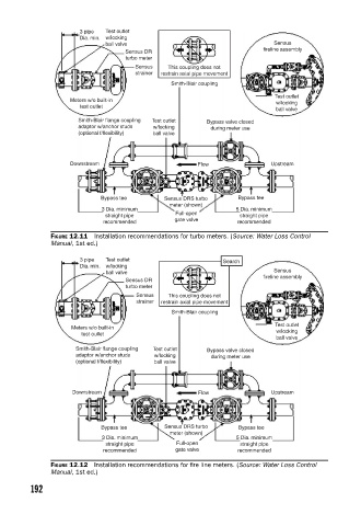
3 pipe  Test outlet
                            Dia. min.  w/locking
                                   ball valve                                  Sensus
                                                                            fireline assembly
                                        Sensus DR
                                        turbo meter
                                          Sensus   This coupling does not
                                          strainer  restrain axial pipe movement
                                                    Smith-Blair coupling
                                                                               Test outlet
                         Meters w/o built-in                                   w/locking
                            test outlet
                                                                               ball valve
                           Smith-Blair flange coupling  Test outlet  Bypass valve closed
                           adaptor w/anchor studs  w/locking  during meter use
                           (optional f/flexibility)  ball valve


                         Downstream                        Flow               Upstream


                                 Bypass tee       Sensus DRS turbo   Bypass tee
                                                   meter (shown)
                                  3 Dia. minimum                     5 Dia. minimum
                                   straight pipe     Full-open        straight pipe
                                                     gate valve
                                  recommended                        recommended
                    FIGURE 12.11  Installation recommendations for turbo meters. (Source: Water Loss Control
                    Manual, 1st ed.)

                            3 pipe  Test outlet                  Search
                            Dia. min.  w/locking
                                                                               Sensus
                                   ball valve
                                                                            fireline assembly
                                        Sensus DR
                                        turbo meter
                                           Sensus  This coupling does not
                                           strainer  restrain axial pipe movement
                                                    Smith-Blair coupling
                                                                               Test outlet
                          Meters w/o built-in                                  w/locking
                            test oullet
                                                                               ball valve
                           Smith-Blair flange coupling  Test outlet  Bypass valve closed
                           adaptor w/anchor studs  w/locking  during meter use
                           (optional f/flexibility)  ball valve


                          Downstream                       Flow               Upstream


                                 Bypass tee       Sensus DRS turbo   Bypass tee
                                                   meter (shown)
                                  3 Dia. minimum                     5 Dia. minimum
                                   straight pipe     Full-open        straight pipe
                                  recommended        gate valve      recommended
                    FIGURE 12.12  Installation recommendations for fi re line meters. (Source: Water Loss Control
                    Manual, 1st ed.)

               192