
Page 224 - Water Loss Control
P. 224
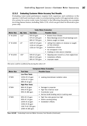
Contr olling Appar ent Losses—Customer Meter Inaccuracy       197


                    12.5.2  Evaluating Customer Meter Accuracy Test Results
                    Evaluating water meter performance requires both experience and confidence in the
                    operator’s skill and training in order to correlate testing results with appropriate correc-
                    tive actions for a given water meter. Included in the following discussion are examples
                    involving Sensus meters, including Table 12.10, which are provided for illustrative pur-
                    poses only.


                                             Turbo Meter Evaluation
                Meter Size   Adj. Vane  Test Data       Possible Cause
                4" W-1000    +15°      90% @ gpm        • Broken Rotor Blades
                                       97% @ 100 gpm    • Rotor Bearings and/or thrust bearings worn
                                       99% @ 700 gpm    • Debris caught on blade
                4" W-1000    +5°       100% @ 10 gpm    • Jetting from debris (in strainer or caught
                                       103% @ 100 gpm     on flow strainer)
                                       105% @ 700 gpm   • Installation effects
                                                        • Air entrapped in line
                                                        • Coating on rotor and/or chamber
                4" W-1000    +30°      94% @ 10 gpm     • Adjusting vane moved to (−) from original test
                                       98% @ 100 gpm    • Installation effects
                                       99% @ 700 gpm    • Improper repair

               This meter could be recalibrated by moving the value to 0°.

                                           Compound Meter Evaluation
                Meter Size    Test Data          Possible Cause
                              Low Flow Tests
                3"SRH         105% @ 0.5 gpm     • Leaking downstream isolation valve
                              102% @ 3.4 gpm
                              98% @ 10 gpm
                              High Flow Tests
                3"SRH         88% @ 25 gpm       • Damage to propeller
                              94% @ 55 gpm       • High flow chamber wear
                              99% @ 280 gpm      • Coordinator wear
                                                 • Vertical shaft binding and/or bushing wear
                3"SRH         95% @ 0.5 gpm      • High flow side geared too high
                              99% @ 3.4 gpm      • Debris causing jetting
                              100% @ 10 gpm      • Installation effects
                              106% @ 25 gpm
                              108.7% @ 150 gpm
                              108% @ 280 gpm

               TABLE 12.10  Evaluating Customer Meter Accuracy Test Results (Continued)