
Page 222 - Water Loss Control
P. 222
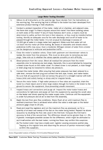
Contr olling Appar ent Losses—Customer Meter Inaccuracy       195


                                          Large Meter Testing Checklist
                1.    Adhere to all instructions on the warning tag. Never deviate from the instructions on
                      the warning tag. The warning tag that is affixed to the tester has been developed from
                      extensive product testing in field situations.
                2.    Conduct a pretest inspection of the meter, meter pit or chamber, and adjacent area.
                      Are there test plugs? Is there a bypass around the meter? Are there isolating valves
                      on both sides of the meter? If any of these features don’t exist, a means must be
                      determined to safely perform the test in their absence, or they must be installed before
                      testing. Identify an adequate area for the safe discharge and run-off of water to be
                      passed through the meter tester. It is not unusual to discharge in excess of
                      10,000 gal of water in a large meter test segment. Make sure that water will not
                      run back into the meter pit while testing. Be aware of sidewalks and streets where
                      pedestrian traffic may occur. Even a moderate 300-gpm stream of water from a tester
                      can be dangerous to vehicular and pedestrian traffic.
                3.    Close the meter’s isolation valves. Close both upstream and downstream valves to
                      isolate the meter from line pressure. This must be done prior to removing any test
                      plugs. Take note as to whether the valves operate smoothly or with difficulty.
                4.    Bleed pressure from the meter. Bleed all residual line pressure from the meter
                      assembly prior to removing any test plugs. Generally, this is accomplished by loosening
                      a bleed screw found on the meter cover. If a bleed screw is not present, a main flange
                      or drain plug may be loosened to relieve any pressure.
                5.    Connect the meter tester. After ensuring that water pressure has been relieved to a
                      safe level, remove the test plug and connect the test pipe, hoses, and meter tester.
                      Be sure that all equipment is laid out across the ground in a straight manner with both
                      hoses (inlet and outlet) having no sharp and/or irregular bends.
                6.    Secure the meter tester. If high water pressure or flow rates are expected, chain the
                      tester to a fixed object and/or drive large stakes through the holes in the tester to the
                      ground to secure the equipment, thus preventing unsafe movement.
                7.    Inspect hoses and connections and purge air. Inspect the meter tester hoses and
                      connections for tightness and purge air from the equipment by opening the small valve
                      on the tester and slowly opening the meter supply valve. Continue until the equipment
                      is under full pressure and all air is bled from the assembly.
                8.    Begin the test from zero flow conditions. Slowly flush all air until maximum flow is
                      reached (maximum flow is achieved when either the valve is wide open or the tester
                      pressure gage drops to 20 psi).
                9.    Read and reset the registers and run the maximum flow as previously run for a
                      quantity of at least one sweep of the dial on the meter being tested. Repeat the above
                      sequence by doubling the flow rate used in the first test. Compare the first test’s
                      accuracy to that of the second test. The difference should not be greater than +/– 5%.
                      If greater, investigate possible causes for the difference, which might be attributed to:
                      (a) A malfunction with the test meter; running low flows may confirm this suspicion.
                      (b) The tested meter may have a badly worn register causing excessive pointer play.
                         Tapping on the register lens and observing the amount of pointer movement might
                         confirm this suspicion.

               Source: Expanded version of Section 14.3.4 Control Manual 1st ed.

               TABLE 12.9  Customer Meter Testing: Procedure and Safety Checklist (Continued).