Page 127 - Water and wastewater engineering
P. 127

3-24   WATER AND WASTEWATER ENGINEERING
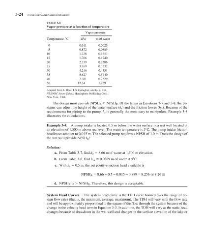
                            TABLE 3-8
                              Vapor pressure as a function of temperature
                                                  Vapor pressure
                            Temperature, 	C    kPa      m of water
                             0                 0.611      0.0623
                             5                 0.872      0.0889
                            10                 1.228      0.1253
                            15                 1.706      0.1740
                            20                 2.339      0.2386
                            25                 3.169      0.3232
                            30                 4.246      0.4331
                            35                 5.627      0.5740
                            40                 7.381      0.7529
                            50                12.34       1.259
                            Adapted from L. Haar, J. S. Gallagher, and G. S. Kell,
                              NBS/NRC Steam Tables,  Hemisphere Publishing Corp.,
                            New York, 1984.
                                The design must provide NPSH  A       NPSH  R  . Of the terms in Equations 3-7 and 3-8, the de-
                            signer can adjust the height of the water surface ( h    s   ) and the friction losses ( h    fs   ). Because of the
                            requirements for piping to the pump,  h    s    is generally the most easy to manipulate. Example 3-4
                            illustrates the calculations.


                              Example 3-4.   A pump intake is located 0.5 m below the water surface in a wet well located at

                            an elevation of 1,500 m above sea level. The water temperature is 5  	 C. The pump intake friction
                            headlosses amount to 0.015 m. The selected pump requires a NPSH of 1.0 m. Does the design of
                            the wet well provide NPSH  R  ?


                              Solution:
                                                ,
                                  a.  From  Table 3-7  find  h    a        8.66 m of water at 1,500 m elevation.

                                 b.  From  Table 3-8 , find  h    va        0.0889 m of water at 5 	 C.
                                 c.  With  h    s        0.5 m, the net positive suction head available is

                                                                     .
                                                                .
                                                                                           .
                                                                                   .
                                                                            .
                                                          .
                                                NPSH A  866   0 5   0015  0 889   8 256  or 8 26  m
                                 d.  NPSH  A   is   NPSH  R  . Therefore, this design is acceptable.
                              System Head Curves.  The system head curve is the TDH curve formed over the range of de-
                            sign flow rates (that is, the minimum, average, maximum). The TDH will vary with the flow rate
                            and will be approximately proportional to the square of the flow through the system because of the
                            change in the velocity head term in Equation 3-3. In addition, the TDH will vary as the static head
                            changes because of drawdown in the wet well and changes in the surface elevation of the lake or
   122   123   124   125   126   127   128   129   130   131   132