
Page 130 - Water and wastewater engineering
P. 130
INTAKE STRUCTURES 3-27
Pumps are selected from those commonly available from pump manufacturers. This then
becomes a problem of matching a pump characteristic or head-discharge curve from a pump
manufacturer’s catalog or database to the system head curve.
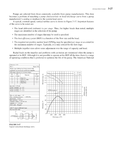
A typical, constant speed, vertical turbine curve is shown in Figure 3-17 . Important features
of the curve to be noted are:
• The head delivered (ordinate) is per stage. Thus, for higher heads than noted, multiple
stages are identified in the selection of the pump.
• The maximum number of stages that may be used is specified.
• The best efficiency point (BEP) is a function of the flow rate and the head.
• The required net positive suction head (NPSH R ) may be specified per stage or as a total for
the maximum number of stages. Typically, it is only critical for the first stage.
• Multiple impeller sizes allow some adjustment over the range of capacity and head.
Radial loads on the impeller and problems with cavitation are minimized when the pump is
operated at its BEP. Although it is not possible to operate at the BEP all the time, there is a range
of operating conditions that is preferred to optimize the life of the pump. The American National
Curve no. 3-18
Size 1 Rpm 1750
Single-stage lab head and horse-power with
enameled cast iron bowls and bronze impeller
Effieciency shown for 2 or more stages A 32 cm
No. Eff. Eff. B 31 cm
stages change Material change 4.0
1 1 Imp.-C.I. 0 3.0
2 0 Imp.-C.I. Enn 0 Head per stage, m 2.0 A
3 0 Bowl-C.I. 1
4 0 Bowl-Brz. 1 1.0 B
Eye area 32 cm
Thurst constang - A 2.3 2
Thurst constang - B 2.3
Thurst constang - C 2.3 NPSH required
1 NPSH required at pump inlet, m
Max. no. std. stages 35 80 0
Max. operating pressure 3,900 kPa
Std. lateral 0.375
Std. shaft dia. 2.0 cm 60
Impeller number P-2397-10 A
Impeller wt. 25.0 kg
Bowl conn. - flanged Efficiency, % 40
Add 37 cm per additional stage
Enclosed line shaft 20
72 cm
0 100 200 300 400
35 cm Discharge, m /h
3
FIGURE 3-17
Typical vertical head-discharge curve.