Page 132 - Water and wastewater engineering
P. 132

INTAKE STRUCTURES 3-29

                                                         3
               e. From  Figure 3-16 , the maximum TDH at 250 m  /h is 18.4 m.
                  The specific speed is

                                                              .
                                                          3  0 5
                                                    .
                                        (1750 rpm )(0 0694 m /s )  4 461 0
                                         ,
                                                                     .
                                    n                 .
                                     s
                                                                    .
                                               (18 4 . m ) 075     888
                                         5192
                                          .
               f. For specific speeds less than 87, the POR is from 70 to 120 percent of the BEP flow rate or
                                                     3
                                                               3
                                                       )
                                           .
                                         (070 )(250 m /h   175 m /h
                 to
                                                               3
                                                    3
                                            .
                                                       )
                                          (12 )(250 m /h    300 m /h
              g. The pump curve is plotted on the system curve in  Figure 3-18  .
                     h.  Using Equation 3-3, the motor brake power is
                                                    3         3
                                           .
                                         (9 807 kN/m  )(0 0694 m /s )(18 m )
                                                       .
                                     P
                                                      078
                                                       .
                                        15 7 . kW
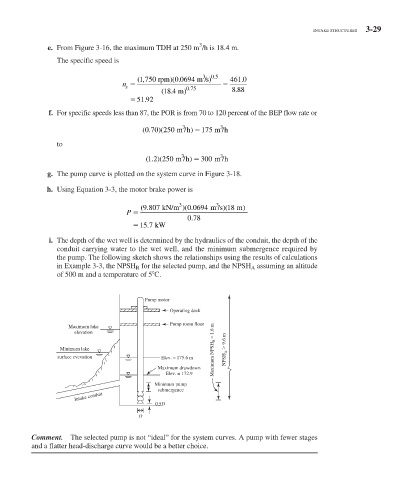
               i.  The depth of the wet well is determined by the hydraulics of the conduit, the depth of the
                 conduit carrying water to the wet well, and the minimum submergence required by
                 the pump. The following sketch shows the relationships using the results of calculations
                 in Example 3-3, the NPSH  R   for the selected pump, and the NPSH  A   assuming an altitude

                 of 500 m and a temperature of 5  	 C.
                                          Pump motor
                                                 Operating deck
                                                 Pump room floor
                    Maximum lake
                      elevation

                  Minimum lake                               Maximum NPSH R  = 1.6 m  NPSH A    9.6 m
                 surface evevation             Elev. = 175.6 m
                                              Maximum drawdown
                                                Elev. = 172.9
                                             Minimum pump
                                              submergence
                      Intake conduit
                                             0.5D
                                        D


            Comment.   The selected pump is not “ideal” for the system curves. A pump with fewer stages
          and a flatter head-discharge curve would be a better choice.
   127   128   129   130   131   132   133   134   135   136   137