
Page 135 - Water and wastewater engineering
P. 135
3-32 WATER AND WASTEWATER ENGINEERING
L
0.3 L 0.08 L
0.1 L
0.25 L
Diffuser
wall
Plan
Screen
Walkway
D
70°
Profile
Baffle
wall
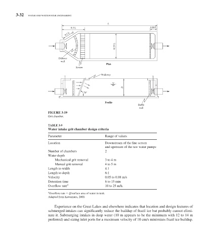
FIGURE 3-19
Grit chamber.
TABLE 3-9
Water intake grit chamber design criteria
Parameter Range of values
Location Downstream of the fine screen
and upstream of the raw water pumps
Number of chambers 2
Water depth
Mechanical grit removal 3 to 4 m
Manual grit removal 4 to 5 m
Length to width 4:1
Length to depth 6:1
Velocity 0.05 to 0.08 m/s
Detention time 6 to 15 min
Overflow rate a 10 to 25 m/h.
a
Overflow rate Q /surface area of water in tank.
Adapted from Kawamura, 2000.
Experience on the Great Lakes and elsewhere indicates that location and design features of
submerged intakes can significantly reduce the buildup of frazil ice but probably cannot elimi-
nate it. Submerging intakes in deep water (10 m appears to be the minimum with 12 to 14 m
preferred) and sizing inlet ports for a maximum velocity of 10 cm/s minimizes frazil ice buildup.