
Page 133 - Water and wastewater engineering
P. 133
3-30 WATER AND WASTEWATER ENGINEERING
20
Pump
curve
Lower
19
operating Maximum
point
total
head
Total dynamic head, m 17 Preferred
∗
18
BEP
slope of
pump curve
Minimum
16
total
head
15
POR
Upper operating point
3,000 6,000 12,000
3
Flow rate, m ⁄d
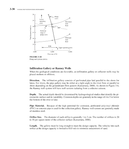
FIGURE 3-18
Pump and system curves.
Infiltration Gallery or Ranney Wells
When the geological conditions are favorable, an infiltration gallery or collector wells may be
placed onshore or offshore.
Direction. The infiltration gallery consists of perforated pipe laid parallel to the shore for
lakes. For rivers, the pipe gallery may be either at a right angle to the river flow or parallel to
shore depending on the groundwater flow pattern (Kawamura, 2000). As shown in Figure 3-6 ,
the Ranney well system will have well screens radiating from a collector caisson.
Depth. The actual depth should be determined by hydrogeological studies that identify the pi-
ezometric surface and its variability. Common depths are generally in the range of 4 to 5 m below
the bottom of the river or lake.
Pipe Material. Because of the high potential for corrosion, perforated polyvinyl chloride
(PVC) or concrete pipe is used for the collection gallery. Ranney well screens are generally made
of stainless steel.
Orifice Size. The diameter of each orifice is generally 1 to 2 cm. The number of orifices is 20
to 30 per square meter of the collector surface (Kawamura, 2000).
Length. The gallery must be long enough to meet the design capacity. The velocity into each
orifice at the design capacity is limited to 0.03 m/s to minimize entrainment of sand.