
Page 51 - Welding Robots Technology, System Issues, and Applications
P. 51
Welding Robots
36
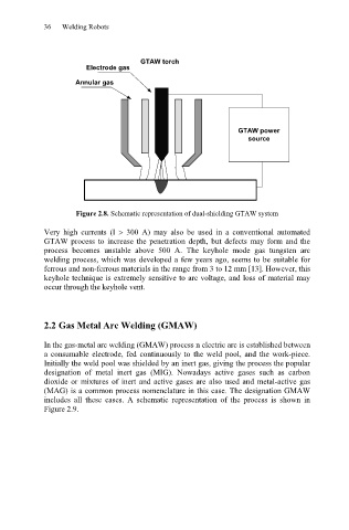
GTAW torch
Electrode gas
Annular gas
GTAW power
source
Figure 2.8. Schematic representation of dual-shielding GTAW system
Very high currents (I ! 300 A) may also be used in a conventional automated
GTAW process to increase the penetration depth, but defects may form and the
process becomes unstable above 500 A. The keyhole mode gas tungsten arc
welding process, which was developed a few years ago, seems to be suitable for
ferrous and non-ferrous materials in the range from 3 to 12 mm [13]. However, this
keyhole technique is extremely sensitive to arc voltage, and loss of material may
occur through the keyhole vent.
2.2 Gas Metal Arc Welding (GMAW)
In the gas-metal arc welding (GMAW) process n electric arc is established between
a consumable electrode, fed continuously to the weld pool, and the work-piece.
Initially the weld pool was shielded by an inert gas, giving the process the popular
designation of metal inert gas (MIG). Nowadays active gases such as carbon
dioxide or mixtures of inert and active gases are also used and metal-active gas
(MAG) is a common process nomenclature in this case. The designation GMAW
includes all these cases. A schematic representation of the process is shown in
Figure 2.9.