
Page 54 - Welding Robots Technology, System Issues, and Applications
P. 54
Welding Technology
power source
arc
characteristic L 2 characteristic 39
Voltage L 1
working point
burn-off rate B I 2 I 1
B 1
2
Current
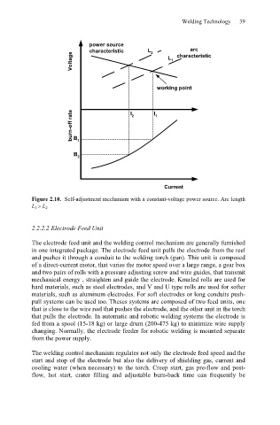
Figure 2.10. Self-adjustment mechanism with a constant-voltage power source. Arc length
L 1 ! L 2
2.2.2.2 Electrode Feed Unit
The electrode feed unit and the welding control mechanism are generally furnished
in one integrated package. The electrode feed unit pulls the electrode from the reel
and pushes it through a conduit to the welding torch (gun). This unit is composed
of a direct-current motor, that varies the motor speed over a large range, a gear box
and two pairs of rolls with a pressure adjusting screw and wire guides, that transmit
mechanical energy , straighten and guide the electrode. Knurled rolls are used for
hard materials, such as steel electrodes, and V and U type rolls are used for softer
materials, such as aluminum electrodes. For soft electrodes or long conduits push-
pull systems can be used too. Theses systems are composed of two feed units, one
that is close to the wire reel that pushes the electrode, and the other unit in the torch
that pulls the electrode. In automatic and robotic welding systems the electrode is
fed from a spool (15-18 kg) or large drum (200-475 kg) to minimize wire supply
changing. Normally, the electrode feeder for robotic welding is mounted separate
from the power supply.
The welding control mechanism regulates not only the electrode feed speed and the
start and stop of the electrode but also the delivery of shielding gas, current and
cooling water (when necessary) to the torch. Creep start, gas pre-flow and post-
flow, hot start, crater filling and adjustable burn-back time can frequently be