
Page 93 - Welding Robots Technology, System Issues, and Applications
P. 93
Sensors for Welding Robots
79
A laser beam is focused on an object, and then the reflection from the object as
seen from a lens in the laser sensor is determined by the distance between the
sensor and the object. If the object is close to the sensor then the angle between the
outgoing beam and the reflection through the focusing lens of the detector is large,
while it is small if the object is farther away. The detection of the distance between
the sensor and object is made by focusing the incoming beam on a detector, in
most cases a CCD array. Depending on which of the pixels of the array are
illuminated, it is possible to calculate the distance to the object.
Depending on the weld joint preparation and geometrical shape, the laser beam can
produce reflections like mirrors. Consider for example a V-groove weld joint
where the laser light will produce several reflecting positions but with different
intensities depending on the surfaces of the weld joint. Therefore, these sensors
must have real time image processing capabilities to filter out reflections that do
not belong to the point of interest. It should be noted in this context that highly
reflective materials may cause problems during welding and a real test may be
needed to verify the functionality.
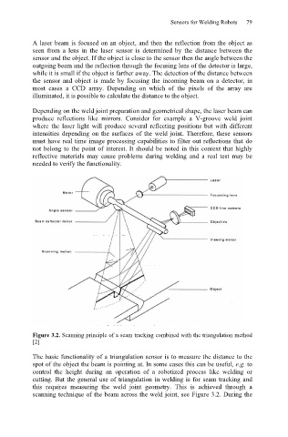
Figure 3.2. Scanning principle of a seam tracking combined with the triangulation method
[2]
The basic functionality of a triangulation sensor is to measure the distance to the
spot of the object the beam is pointing at. In some cases this can be useful, e.g. to
control the height during an operation of a robotized process like welding or
cutting. But the general use of triangulation in welding is for seam tracking and
this requires measuring the weld joint geometry. This is achieved through a
scanning technique of the beam across the weld joint, see Figure 3.2. During the