
Page 94 - Welding Robots Technology, System Issues, and Applications
P. 94
Welding Robots
80
scanning, the sensor acquires a two-dimensional picture of the joint profile as an
array of 2D coordinates. When the robot is moving, a weld joint geometrical model
can be made that contains a full 3D description of the joint which is created during
the welding operation when the sensor is moved along the joint.
If a laser stripe is projected onto the object and sensed by a 2D CCD array, the
image information can be used directly without moving the robot. This is a
technique that is useful if the stripe is circular and aimed at a corner. Then, the
corner and its walls can be located from one position of the robot only, compared
with the more time consuming traditional technique of measuring the location of
one wall at a time.
In most cases, optical seam trackers based on triangulation are used to keep the
robot “on track” with the weld joint during welding in real time. However, these
sensors have a capability for more than that, and information that can in most cases
be achieved that include joint volume, gap size, misalignment, tack welds, etc. This
information is useful for adaptive feed-back control of both the welding power
source and the robot to perform the task in accordance with the predefined
specifications of the welds to be produced. As an example, the travel speed of the
welding gun defined by the robot can be controlled with respect to the gap of the
weld and the welding power related parameters in combination.
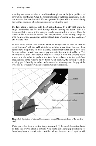
Figure 3.3. Illustration of a typical laser scanner sensor [3] mounted ahead of the welding
torch
If the gap varies, there are a few things to control: (i) the metal deposition should
be done in a way to obtain a constant weld shape, (ii) a large gap is sensitive for
burn-through and a control action could be to lower the travel speed together with