
Page 163 - Well Control for Completions and Interventions
P. 163
Well Control Surface Equipment 155
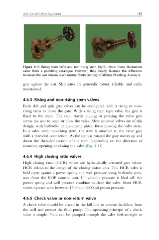
Figure 4.11 Rising stem (left) and non-rising stem (right). Note: these illustrations
came from a plumbing catalogue. However, they clearly illustrate the difference
between the two closure mechanisms. Photo courtesy of Michels Plumbing, Aurora, IL.
gate against the seat. Slab gates are generally robust, reliable, and easily
maintained.
4.6.3 Rising and non-rising stem valves
Both slab and split gate valves can be configured with a rising or non-
rising stem to move the gate. With a rising stem type valve, the gate is
fixed to the stem. The stem travels pulling or pushing the valve gate
across the seat to open or close the valve. Most actuated valves are of this
design, with hydraulic or pneumatic piston force moving the valve stem.
In a valve with non-rising stem, the stem is attached to the valve gate
with a threaded connection. As the stem is rotated the gate moves up and
down the threaded section of the stem (depending on the direction of
rotation), opening or closing the valve (Fig. 4.11).
4.6.4 High closing ratio valves
High closing ratio (HCR) valves are hydraulically actuated gate valves.
HCR relates to the design of the closing piston area. The HCR valve is
held open against a power spring and well pressure using hydraulic pres-
sure from the BOP control unit. If hydraulic pressure is bled off, the
power spring and well pressure combine to close the valve. Most HCR
valves operate with between 1500 and 3000 psi piston pressure.
4.6.5 Check valve or non-return valve
A check valve should be placed in the kill line to prevent backflow from
the well and protect the fluid pump. The operating principal of a check
valve is simple. Fluid can be pumped through the valve (left-to-right in