
Page 160 - Well Control for Completions and Interventions
P. 160
152 Well Control for Completions and Interventions
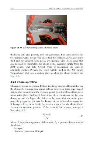
Figure 4.8 MI type remotely operated adjustable choke.
displaying drill pipe pressure and casing pressure. The panel should also
be equipped with a stroke counter, so that the operator knows how much
fluid has been pumped. Most panels are equipped with a hand pump that
can be used to manipulate the choke if the hydraulic supply from the
BOP control unit fails. Several types of mechanism are used in
adjustable chokes. Perhaps the most widely used is the MI Swaco
“Superchoke” that uses a rotating plate to adjust the choke (orifice) size
(Fig. 4.8).
4.5.4 Choke operation
Chokes are prone to erosion. If there is a large pressure differential across
the choke, the pressure drop causes bubbles to form as liquid vaporizes. A
little further downstream (the recovery point) these bubbles collapse; cavi-
tation takes place. Prolonged flow under these conditions can be very
damaging, and the bigger the difference between inlet and outlet pres-
sures, the greater the potential for damage. A rule of thumb to determine
if damage is likely is to divide the pressure drop across the choke (Delta
P) over the upstream pressure. If the result is 0.6 or more, damage is
likely (Fig. 4.9).
P u 2 P d
(4.1)
P u
where P u is pressure upstream of the choke; P d is pressure downstream of
the choke.
Example:
Upstream pressure 5 6500 psi.