
Page 156 - Well Control for Completions and Interventions
P. 156
148 Well Control for Completions and Interventions
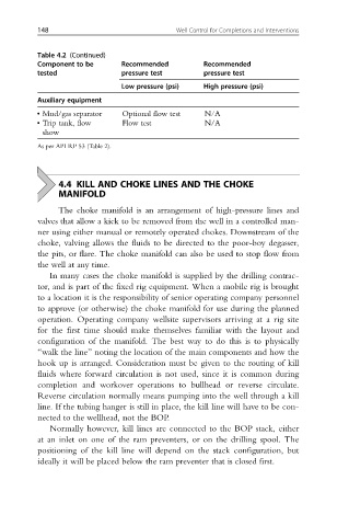
Table 4.2 (Continued)
Component to be Recommended Recommended
tested pressure test pressure test
Low pressure (psi) High pressure (psi)
Auxiliary equipment
• Mud/gas separator Optional flow test N/A
• Trip tank, flow Flow test N/A
show
As per API RP 53 (Table 2).
4.4 KILL AND CHOKE LINES AND THE CHOKE
MANIFOLD
The choke manifold is an arrangement of high-pressure lines and
valves that allow a kick to be removed from the well in a controlled man-
ner using either manual or remotely operated chokes. Downstream of the
choke, valving allows the fluids to be directed to the poor-boy degasser,
the pits, or flare. The choke manifold can also be used to stop flow from
the well at any time.
In many cases the choke manifold is supplied by the drilling contrac-
tor, and is part of the fixed rig equipment. When a mobile rig is brought
to a location it is the responsibility of senior operating company personnel
to approve (or otherwise) the choke manifold for use during the planned
operation. Operating company wellsite supervisors arriving at a rig site
for the first time should make themselves familiar with the layout and
configuration of the manifold. The best way to do this is to physically
“walk the line” noting the location of the main components and how the
hook up is arranged. Consideration must be given to the routing of kill
fluids where forward circulation is not used, since it is common during
completion and workover operations to bullhead or reverse circulate.
Reverse circulation normally means pumping into the well through a kill
line. If the tubing hanger is still in place, the kill line will have to be con-
nected to the wellhead, not the BOP.
Normally however, kill lines are connected to the BOP stack, either
at an inlet on one of the ram preventers, or on the drilling spool. The
positioning of the kill line will depend on the stack configuration, but
ideally it will be placed below the ram preventer that is closed first.