
Page 180 - Fluid Power Engineering
P. 180
Advanced W ind Resource Assessment 153
where s i is the length of each segment with slope above the critical
slope.
The difference between RIX at the turbine location and RIX at the
met-tower location is called the delta RIX:
RIX = RIX WTG − RIX met
In terms of RIX, spatial extrapolation using WAsP is recommended
only when the RIX between measured and predicted sites is close to
2
2
zero or, at most, 5%. For higher values of RIX, Mortensen et al. report
a log-linear relationships between ratio of wind speed and delta RIX
based on empirical data for a site in Portugal with a high coefficient
2
of determination, R . Furthermore, it is reported that the relationship
is insensitive to radius, critical slope (0.3 – 0.45), and sector-specific
RIX.
v p
ln = 1.508 RIX (8-8)
v m
AEP p
ln = 5.175 RIX (8-9)
AEP m
where v p , v m are predicted and measured wind speed, and AEP p ,
AEP m are predicted and measured average annual energy production.
The above equations provide a method for spatial extrapolation for
cases with difference in ruggedness.
The universality of the equations and the constants is uncertain
and site-specific validation is recommended. Dependence of the con-
stants on the directional sectors must also be validated.
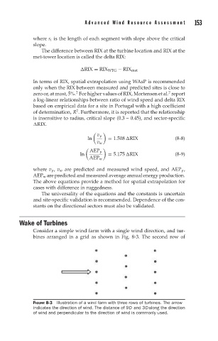
Wake of Turbines
Consider a simple wind farm with a single wind direction, and tur-
bines arranged in a grid as shown in Fig. 8-3. The second row of
FIGURE 8-3 Illustration of a wind farm with three rows of turbines. The arrow
indicates the direction of wind. The distance of 9D and 3Dalong the direction
of wind and perpendicular to the direction of wind is commonly used.