
Page 157 - Wind Energy Handbook
P. 157
THE METHOD OF ACCELERATION POTENTIAL 131
The second pressure distribution is, therefore,
1 0 p ffiffiffiffiffiffiffiffiffiffiffiffiffiffi 2
2
p 2 ( ì) ¼ C 3 1 ì (2 5ì ) (3:165)
3
The sum of the two pressure distributions must be zero where ì ¼ 0, so
9
0
C ¼ C T
3
4
and the combination of the two distributions is
15 p ffiffiffiffiffiffiffiffiffiffiffiffiffiffi
p 1 2 ( ì) ¼ C T ì 2 1 ì 2 (3:166)
4
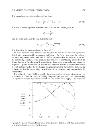
The three distributions are shown in Figure 3.71.
As most modern wind turbines are designed to achieve as uniform a pressure
distribution as practicable, to maximize efficiency, the form chosen for the helicop-
ter rotor might need to be modified. A uniform pressure distribution can be formed
by combining solutions but, because the pressure discontinuity must itself be
discontinuous at the disc edge, it would mean that a great many solutions would be
required. Tip-loss effects would require zero pressure at both the blade tips and at
the hub but for most of the blade span the pressure should be uniform. It should be
pointed out that the blade loading caused by uniform pressure does increase linearly
with radius.
The induced velocity field caused by the axisymmetric pressure distribution has
to be obtained from the pressure field by integrating Equations (3.145) commencing
far upstream where free-stream conditions are assumed to apply. The upstream
1.5
1.0
p (µ)
1
0.5
p (µ)
2
0.0
p (µ)
12
-0.5
-1.0
0 0.2 0.4 0.6 0.8 1
µ
Figure 3.71 Radial Pressure Distributions of the First Two Solutions and their Combination
to Satisfy the Requirements at the Rotor Axis