
Page 346 - Wind Energy Handbook
P. 346
320 DESIGN LOADS FOR HORIZONTAL-AXIS WIND TURBINES
1
0.9
0.8
0.7
Size redcution factor 0.6 Tapered blade ‘TR’
0.5
0.4
0.3
Blade of constant cross section
0.2
0.1
0
0 0.5 1 1.5 2 2.5 3
First mode natural frequency (Hz)
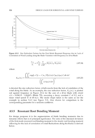
Figure A5.2 Size Reduction Factors for the First Mode Resonant Response due to Lack of
Correlation of Wind Loading along the Blade-Variation with Frequency for 20 m Blade
ó x1 ó u ð p ffiffiffiffiffiffiffiffiffiffiffiffiffiffi ffiffiffiffiffiffiffiffiffiffiffiffiffiffiffiffip
¼ 2 p ffiffiffiffiffiffi R u (n 1 ) K Sx (n 1 ) (A5:24)
x 1 U 2ä
where
ð ð
R R
exp [ Cjr r9jn 1 =U]c(r)c(r9)ì 1 (r)ì 1 (r9)dr dr9
K Sx (n 1 ) ¼ 0 0 ! (A5:25)
ð 2
R
c(r)ì 1 (r)dr
0
is denoted the size reduction factor, which results from the lack of correlation of the
wind along the blade. As an example, the size reduction factor, K Sx (n 1 ), is plotted
out against frequency in Figure A5.2 for the case of a 20 m blade with chord
c(r) ¼ 0:0961R 0:06467r (Blade TR), assuming a decay constant C of 9.2, and a
mean wind speed U of 45 m=s. The mode shape taken is the same as for the
example in section 5.6.3 (see Figure 5.3). Also shown for comparison is the
corresponding parameter for a uniform cantilever.
A5.5 Resonant Root Bending Moment
For design purposes it is the augmentation of blade bending moments due to
dynamic effects that is of principal significance. The ratio of the standard deviation
of the first mode resonant root bending moment to the steady root bending moment
(allowing for the lack of correlation of wind fluctuations along the blade) is derived
below.