
Page 405 - Wind Energy Handbook
P. 405
BLADES 379
7.1.3 Practical modifications to optimum design
The result of the optimization described in the previous section is typically a blade
geometry in which both blade chord and blade twist vary approximately inversely
with radius, as illustrated in Figure 3.19. However, because the inboard section of
the blade makes only a small contribution to total power output (Figure 3.30), the
aerofoil section is generally not continued inboard of about 15 percent radius in
practice, and the chord at this radius is substantially reduced, to perhaps half the
theoretical optimum. It is then often found expedient to taper the chord uniformly
over the active length of the blade, with the tip chord and chord taper set so that the
chord distribution approximates closely to the optimum over the outboard half of
the blade (Figure 3.20).
The blade root area is normally circular in cross section in order to match up with
the pitch bearing in the case of pitchable blades, or to allow pitch angle adjustment at
the bolted flange (to compensate for non-standard air density) in the case of stall-
regulated blades. The transition from the root section to the aerofoil section outboard
of 15 percent radius should be a smooth one for structural reasons, with the result that
the latter section will have a high thickness to chord ratio of up to about 50 percent.
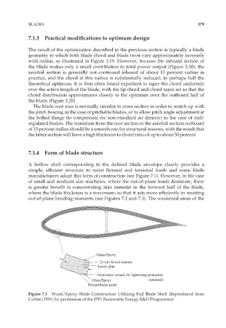
7.1.4 Form of blade structure
A hollow shell corresponding to the defined blade envelope clearly provides a
simple, efficient structure to resist flexural and torsional loads and some blade
manufacturers adopt this form of construction (see Figure 7.1). However, in the case
of small and medium size machines, where the out-of-plane loads dominate, there
is greater benefit in concentrating skin material in the forward half of the blade,
where the blade thickness is a maximum, so that it acts more efficiently in resisting
out-of-plane bending moments (see Figures 7.2 and 7.3). The weakened areas of the
Glass/Epoxy
25mm Wood veneers
Epoxy glue
Aluminium screen for lightening protection
Glass/Epoxy (unusual)
Polyurethane point
Figure 7.1 Wood/Epoxy Blade Construction Utilizing Full Blade Shell (Reproduced from
Corbet (1991) by permission of the DT1 Renewable Energy R&D Programme)